Download
1 / 12
150 likes | 470 Views
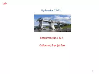
Lab. Hydraulics CE-331. Experiment No.1 & 2. Orifice and free jet flow. EXPERIMENT 1. Objective The objective is to determine the coefficient of velocity (Cv). Method

E N D
Lab Hydraulics CE-331 Experiment No.1 & 2 Orifice and free jet flow
EXPERIMENT 1 Objective The objective is to determine the coefficient of velocity (Cv). Method By measurements of the trajectory of a jet issuing from an orifice in the side of reservoir under steady flow conditions (constant head).
Equipment • Hydraulics bench which allows us to measure flow by timed volume collection. • Orifice and jet apparatus. • Technical data • Diameter of small orifice 3 mm = 0.003 m • Diameter of large orifice 6 mm = 0.006 m
Theory Consider a tank containing a liquid and with an orifice at its side wall at a depth H below the free surface Vena contracta The cross section where the contraction is greatest or where the area of the jet is minimum is called vena contracta. The ratio of area jet Aj at vena contracta to area of orifice Ao is symbolised by coefficient of contraction. Cc = Aj / Ao If we apply the Bernoulli’s equation between two the two points 1 at the free surface and point 2 at the vena contracta:
Theory - Trajectory method The actual velocity (Va) can be determined by measuring the position of a point on the trajectory of a free jet, down stream of the vena contracta.
Procedure • Make sure that the reservoir is positioned across the channel on top of the hydraulic bench, and level the reservoir by the adjustable feet on the base. • Measure and record the diameter of the orifice. • Turn on the pump and open the valve gradually, as the water level rises in the reservoir, adjust the bench valve to give water level 2 to 3 mm above the overflow level. This gives a constant head and produces steady flow through the orifice. • Position the over flow tube to give high head. Note the value of the head. • Determine trajectory of the jet using the needles mounded on the vertical backboard to follow the profile of the jet. • Attach a sheet of paper to the back-board. • Mark the location of the top of each needle on the paper. • Measure the horizontal (x) and vertical (y) distances from the orifice.
Taking a set of result • Orifice diameter • Head • Horizontal distance • Vertical distance • (yh)^0.5 • Slope of X vs (yh)^0.5 • Cv = (average slope/2)
Analysis 1 –Plot X vs. (YH)^0.5 and determine the slop of the graph. Cv = average slop /2 Cv = X / ((2) (YH)^0.5) Report writing
Lab Hydraulics CE-331 Experiment No.2 Orifice and free jet flow 10
Experiment No.2 Objective: The objective is to determine the coefficient of discharge (Cd) and coefficient of contraction (Cc), of two small orifices.
Procedures: • Measure the flow rate using a measuring cylinder for a specific time (5 second). • Note the reservoir head value. • Repeat this procedure for different heads, by adjusting the level of overflow pipe. Experimental Data Analysis 1 – Plot Qa vs. (H)^0.5 and determine the slop of the graph. Cd = slope/(A(2.g)^0.5)