IP Multicasting
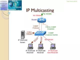
http://munz-udo.de. IP Multicasting. Multicast Topics. IGMP: Internet Group Management Protocol CGMP: Cisco Group Management Protocol PIM: Protocol Independent Multicast JAVVIN. Multimedia traffic using Unicast.

IP Multicasting
E N D
Presentation Transcript
http://munz-udo.de IP Multicasting
Multicast Topics IGMP: Internet Group Management Protocol CGMP: Cisco Group Management Protocol PIM: Protocol Independent Multicast JAVVIN
Multimedia traffic using Unicast • Application sends one copy of each packet to every client's unicast address. • As a result, unicast transmission has significant scaling restrictions. • If the group is large, the same information must be carried multiple times, even on shared links. Best case: known unicasts Worst case: unknown unicasts
Multimedia traffic using Broadcast • Application sends only one copy of each packet using a broadcast. • Inefficient, if only for a small subset of the network. • Every host device must process the broadcast multimedia data frame. • Transmissions may reach data rates as high as 13 Mbps or more. • All devices must still process the broadcast traffic, even if not using it. • May use most, if not all, of the allocated bandwidth for each device. • Cisco highly discourages broadcast implementation for applications delivering data, voice, or video to multiple receivers.
Multimedia traffic using Multicast • The most efficient solution – in between broadcast and unicast. • Server sends one copy of each packet to a special address that represents multiple clients. • Server sends out a single data stream to multiple clients. • Client device decides whether or not to listen to the multicast address. • Saves bandwidth and controls network traffic by forcing the network to replicate packets only when necessary. • Reduces network bandwidth consumption and host processing. • Cisco switches can process IP multicast packets and deliver those packets only to requesting receivers at both Layer 2 and Layer 3.
Less stress on server • In a unicast scenario, the server sequences through transmission of multiple copies of the data, so variability in delivery time is large, especially for large transmissions or large distribution lists.
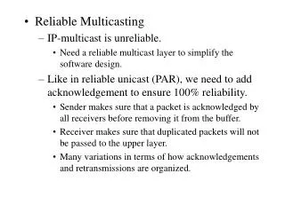
Uses UDP Application Header + data • IP multicast traffic uses UDP as the transport layer. • Unlike TCP, UDP adds no reliability, flow control, or error-recovery functions to IP. • Because of the simplicity of UDP, data-packet headers contain fewer bytes and consume less network overhead than TCP. • Reliability in multicast is therefore managed at the receiving client and by QoS in the network.
IP Multicast Routing • IP multicast uses a virtual group address called the multicast IP address. • IP unicast, a packet is routed from a source address to a destination address, hop by hop. • IP multicast, the packet's destination address is notassigned to a single destination. • Instead, receivers join a group. • All members of the group receive the packet. • A host must be a member of the group to receive the packet. • Multicast sources do not need to be members of that group.
IP Multicast Routing • Packets sent by group member 3 are received by group members 1 and 2, but not by the nonmember of the group. • The nonmember host sends packets to the multicast group that are received by all three group members. • Group members 1 and 2 do not send any multicast packets. • The multicast router sends the packets to respective multiple interfaces to reach all the hosts. • To avoid duplication, several multicast routing protocols use reverse path forwarding (RPF), discussed later.
Multicast IP Address Structure • IP multicast uses the Class D addresses, which range from 224.0.0.0 to 239.255.255.255. • These addresses consist of binary 1110 as the most significant bits (MSBs) in the first octet, followed by a 28-bit group address. • Unlike with Class A, B, and C IP addresses, the last 28 bits of a Class D address are unstructured. 224.0.0.0 to 239.255.255.255
Multicast IP Address Structure • The Internet Assigned Numbers Authority (IANA) controls the assignment of IP multicast addresses. • The Class D address range is used only for the group address or destination address of IP multicast traffic. • The source address for multicast datagrams is always the unicast source address. Destin. IP: Multicast Src. IP: Unicast
Multicast IP Address Structure • Applications allocate multicast addresses dynamically or statically. • Dynamic multicast addressing provides applications with a group address on demand. • Because dynamic multicast addresses have a specific lifetime, applications must request this type of address only for as long as the address is needed. • Statically allocated multicast addresses are reserved for specific protocols that require well-known addresses, such as OSPFHello packets (224.0.0.5, AllSPFRouters). • IANA assigns these well-known addresses, which are called permanent host groups and are similar in concept to the well-known TCP and UDP port numbers.
Reserved Link Local Addresses • 224.0.0.0 to 224.0.0.255 (link local destination addresses) to be used by network protocols on a local network segment. • Routers do not forward packets in this address range. • Typically sent with a Time-to-Live (TTL) value of 1. • Network protocols use these addresses for automatic router discovery and to communicate important routing information. • For example, OSPF uses the IP addresses 224.0.0.5 and 224.0.0.6 to exchange link-state information. • 224.0.0.5, All SPF Routers • 224.0.0.6 ALL DR Routers
Reserved Link Local Addresses • Address 224.0.0.1 identifies the all-hosts group. • Every multicast-capable host must join this group when initializing its IP stack. • If you send an ICMP echo request to this address, all multicast-capable hosts on the network answer the request with an ICMP echo reply. • Address 224.0.0.2 identifies the all-routers group. • Multicast routers join this group on all multicast-enabled interfaces.
mping – A simple demonstration • Use mping on two or more hosts to show how multicast hosts send and receive multicast traffic. • Mping is a little different, in that both hosts are senders and receivers. • http://research.microsoft.com/barc/mbone/mping.aspx Hosts: mping <IP address> [port] [TTL] [time in msec between pings] • Example, both hosts: mping 224.10.10.10 • When it sends a packet: "Sent packet" • When it receives a packet: RCV: XX bytes from XXX.XXX.XXX.XXX
Multicast MAC Address Structure • The destination IP address of IP multicast packets maps to a multicast MAC address. • However, themulticast MAC address is derived from the IP multicast address.
Multicast MAC Address Structure • Multicasts must also have a layer 2 group address (it can’t be FF-FF-FF-FF-FF-FF). • The first 3 bytes (24 bits) of the multicast MAC address are always 01-00-5E. • Binary: 00000001.00000000.01011110.0xxxxxxx.xxxxxxxx.xxxxxxxx with the 25th bit set to 0. • This is a reserved value that indicates a multicast application. • Usually, the first half of the MAC address is the vendor code, aka Organizational Unique Identifier. • So, if multicast L2 addresses always begin with 01-00-5E, where does the other half (24 bits) of the address come from? • “0” + 23 bits (copied from the IP address)
Multicast MAC Address Structure • The second half of the MAC address (24 bits) derives from: 0 + 23 bits (copied from the IP address) • The host copies the last 23 bits of the multicast IP address into the last 23 bits of the MAC address. • Why the conversion? • Host: “If I join multicast group 224.10.8.5, I will listen for the MAC address 01-00-5E-0A-08-05.”
Multicast MAC Address Structure • Because all the IP multicast addresses have the first 4 bits set to 1110, the remaining 28 least significant bits (LSBs) of multicast IP addresses must map into the 23 LSBs of the MAC address. • As a result, the MAC address loses 5 bitsof uniqueness in the IP-to-MAC address mapping process (uniqueness of IP address). Loose 5 bits of IP Address IP:1110xxxx.xxxxxxxx.xxxxxxxx.xxxxxxxx Multicast MAC: 00000001.00000000.01011110.0xxxxxxx.xxxxxxxx.xxxxxxxx
23 bits of the actual IP multicast address get translated into the MAC address. BUT, these 5 bits don’t make it to the MAC address. Every multicast IP address starts with 1110, so this part doesn’t need to be in the MAC address Multicast MAC Address Structure 224 - 239
Multicast MAC Address Structure • This method for mapping multicast IP addresses to MAC addresses results in a 32:1 mapping, whereas each multicast MAC address represents a possible 32 distinct IP multicast addresses. MAC: 00000001.00000000.01011110.00000001.00000001.00000010 IP: 11100000.00000001.00000001.00000010 11100000.10000001.00000001.00000010 11100001.00000001.00000001.00000010 TO 11101111.10000001.00000001.00000010 02
Multicast MAC Address Structure Convert 224.0.9.45 to a multicast MAC address. 224 | 0 | 9 | 45 1110 0000 0000 0000 0000 1001 0010 1101 01-00-5E First 3 bytes 25th bit “0” 0000 0000 0000 1001 0010 1101 0000 0000 0000 1001 0010 1101 01-00-5E- 0 0 - 0 9 - 2 D(13) 01-00-5E-00-09-2D
Multicast MAC Address Structure Convert 224.192.255.44 to a multicast MAC address. 224 | 192 | 255 | 46 1110 0000 1100 0000 1111 1111 0001 1110 01-00-5E First 3 bytes 25th bit “0”0100 0000 1111 1111 0001 1110 0100 0000 1111 1111 0001 1110 01-00-5E- 4 0 - F(15) F - 1 E(14) 01-00-5E-40-FF-1E
Multicast MAC Address Structure 01:00:5E:01:01:02 [IP 224.129.1.2] • A host thatjoins one multicast group programs its network interface card to listen to the IP-mapped MAC address. • If the same MAC address maps to a second MAC multicast address already in use, the host CPU processes both sets of IP multicast frames. IP Mapped Ethernet Multicast Frames 01:00:5E:01:01:02 [IP 225.1.1.2] Joined 224.129.1.2 so NIC is listening for 01-00-5E-01-01-02
Multicast MAC Address Structure 01:00:5E:01:01:02 [IP 224.129.1.2] • For example, multicast IP addresses 224.129.1.2 and 225.1.1.2 both map to the same multicast MAC address 01:00:5E:01:01:01. • As a result, a host that registered to group 224.129.1.2 also receives the traffic from 225.1.1.2 because the same MAC multicast address is used by both IP multicast flows. • It is recommended to avoid overlappingwhen implementing multicast applications in the multilayer switched network by tuning the destination IP multicast address at the application level. • In this case where multiple groups map to the same MAC address, usually higher-layer protocols let hosts interpret which packets are for the application, using UDP port numbers (normally different per application). IP Mapped Ethernet Multicast Frames 01:00:5E:01:01:02 [IP 225.1.1.2] Joined 224.129.1.2 so NIC is listening for 01-00-5E-01-01-02
Multicast MAC Address Structure • Furthermore, because switches forward frames based on the multicast MAC address if configured for Layer 2 multicast snooping, they forward frames to all the members corresponding to other IP multicast addresses of the same MAC address mapping, even if the frames belong to a different IP multicast group. Multicast Traffic:01:00:5E:01:01:02 [IP 224.129.1.2] Multicast Group: 01:00:5E:01:01:02 [IP 225.1.1.2] Multicast Group:01:00:5E:01:01:02 [IP 224.129.1.2]
Reverse Path Forwarding • Multicast-capable routers and multilayer switchescreate distribution trees that control the path that IP multicast traffic takes through the network. • Reverse path forwarding is the mechanism that performs an incoming interface check to determine whether to forward or drop an incoming multicast frame. • RPF is a key concept in multicast forwarding. • This RPF check helps to guarantee that the distribution tree for multicast is loop-free. • In addition, RPF enables routers to correctly forward multicast traffic down the distribution tree.
Reverse Path Forwarding • In unicast routing, traffic is routed through the network along the path from the single source to the single destination host. • A router that is forwarding unicast packets does not consider the source address, by default; the router considers only the destination address and how to forward the traffic toward the destination. • In multicast forwarding, the source is sending traffic to an arbitrary group of hosts that is represented by a single multicast group address. • When a multicast router receives a multicast packet, it determines which direction is the upstream direction (toward the source) and which one is the downstream direction (or direction toward the receivers). • A router forwards a multicast packet only if the packet is received on the correct upstream interface determined by the RPF process.
Reverse Path Forwarding For traffic flowing down a source tree, the RPF check procedure works as follows: • The router looks up the source address in the unicast routing table to determine whether it arrived on the interface that is on the reverse path back to the source. • If the packet has arrived on the interface leading back to the source, the RPF check is successful and the router replicates and forwards the packet to the outgoing interfaces. • If the RPF check in the previous step fails, the router drops the packet and records the drop as an RPF failed drop.
Reverse-Path Forwarding RPF check fails 151.10.3.21 224.1.1.1 • The router in the figure receives a multicast packet from source 151.10.3.21 on interface S0. • A check of the unicast route table shows that this router uses interface S1 as the egress (exit) interface for forwarding unicast data to 151.10.3.21. • Because the packet instead arrived on interface S0, the packet fails the RPF check, and the router drops the packet.
RPF check succeeds 151.10.3.21 224.1.1.1 • With this example, the multicast packet arrives on interface S1. • The router checks the unicast routing table and finds that interface S1 is the correct ingress (incoming) interface. • The RPF check passes, and the router forwards the packet.
Non-RPF Traffic Do Not Forward Source IP Address is not on these interfaces, but interface connected to Campus Network Router. • In multilayer switched networks where multiple routers connect to the same LAN segment, only one PIM-designated router forwards the multicast traffic from the source to the receivers on the outgoing interfaces. • Router A, the PIM-designated router (PIM DR), forwards data to VLAN 1 and VLAN 2. • Router B receives the forwarded multicast traffic on VLAN 1 and VLAN 2, and it drops this traffic because the multicast traffic fails the RPF check. (Source IP is via the other interface.) • Traffic that fails the RPF check is called non-RPF traffic.
Multicast Forwarding Tree Source Tree Shared Tree • Multicast-capable routers create multicast distribution trees that control the path that IP multicast traffic takes through the network to deliver traffic to all receivers. • The following are the two types of distribution trees: • Source trees • Shared trees
Source Trees • The simplest form of a multicast distribution tree is a source tree with its root at the source and its branches forming a tree through the network to the receivers. • Because this tree uses the shortest path through the network, it is also referred to as a shortest path tree (SPT). • SPT for group 224.1.1.1 rooted at the source, host A, and connecting two receivers, hosts B and C.
Source Trees • Using the (S,G) notation, the SPT for the example shown is (192.168.1.1, 224.1.1.1). • The Source-Group (S,G) notation implies that a separate SPT exists for each individual source sending to each group. • For example, if host B is also sending traffic to group 224.1.1.1 and hosts A and C are receivers, a separate (S,G) SPT would exist with a notation of (192.168.2.2, 224.1.1.1).
Shared Trees • The shared unidirectional tree for the group 224.1.1.1 with the shared root located at router D – the RP. • Source traffic is sent toward the RP on a source tree. • The traffic is then forwarded down the shared tree from the RP to reach all the receivers unless the receiver is located between the source and the RP, in which case the multicast traffic is serviced directly. • Unlike source trees, which have their root at the source, shared trees use a single common root placed at some chosen point in the network. • This shared root is called a rendezvous point (RP).
Shared Trees • Because all sources in the multicast group use a common shared tree, a wildcard notation written as (*, G), pronounced “star comma G,” represents the tree. • In this case, * means all sources, and G represents the multicast group. • Therefore, the shared tree shown in the figure is written as: (*, 224.1.1.1).
Comparing:Source Trees • This advantage guarantees the minimum amount of network latency for forwarding multicast traffic. • However, this optimization requires additional overhead because the routers maintain path information for each source. • In a network that has thousands of sources and thousands of groups, this overhead quickly becomes a resource issue on routers or multilayer switches. • Source trees have the advantage of creating the optimal path between the source and the receivers.
Comparing:Shared Trees • Shared trees have the advantage of requiring the minimum amount of state information in each router. • This advantage lowers the overall memory requirements and complexity for a network that only allows shared trees. • The disadvantage of shared trees is that, under certain circumstances, the paths between the source and receivers might not be the optimal paths, which may introduce additional latency in packet delivery. • May overuse some links and leave others unused • For example, the shortest path between host A (source 1) and host B (a receiver) is between router A and router C. • Network designers need to carefully consider the placement of the RP when implementing a shared tree–only environment. Better Path
IP Multicast Routing http://de.wikipedia.org/wiki/Protocol_Independent_Multicast PIM Sparse Mode (spärlich) PIM Dense Mode(dicht) • Similar to IP unicast, IP multicast uses its own routing, management, and Layer 2 protocols. • The following are two important multicast protocols: • Protocol Independent Multicast (PIM) • PIM Dense Mode • PIM Sparse Mode (Sparse-dense mode is most common in large enterprise networks.) • Internet Group Management Protocol (IGMP)
PIM PIM Dense Mode PIM Sparse Mode • A multicast routing protocol is responsible for the construction of multicast delivery trees and enabling multicast packet forwarding. • Different IP multicast routing protocols use different techniques to construct multicast trees and to forward packets. • The PIM routing protocol leverages whichever unicast routing protocols are used to populate the unicast routing table to make multicast forwarding decisions.
PIM PIM Dense Mode PIM Sparse Mode • Routers use the PIM neighbor discovery mechanism to establish PIM neighbors using hello messages to the ALL-PIM-Routers (224.0.0.13) multicast address for building and maintaining PIM multicast distribution trees. • In addition, routers use PIM hello messages to elect the designated router (DR) for a multicast LAN network. • Two distinct versions: PIM version 1 and PIM version 2.
PIM Dense Mode Source Tree • PIM dense mode (PIM-DM) multicast routing protocols relies on: • Periodic flooding of the network with multicast traffic to set up and maintain the distribution tree. • Neighbor information to form the distribution tree. • Source distribution tree to forward multicast traffic • Built by respective routers as soon as any multicast source begins transmitting.
PIM Dense Mode Source Tree • PIM-DM assumes that the multicast group members are densely distributed throughout the network and that bandwidth is plentiful, meaning that almost all hosts on the network belong to the group. • When a router configured for PIM-DM receives a multicast packet: • The router performs the RPF check to validate the correct interface for the source. • Forwards on the packet all the interfaces configured for multicasting until pruning and truncating occurs.
PIM Dense Mode Source Tree • All downstream routers receive the multicast packet until the multicast traffic times out. • PIM-DM sends a pruning message upstream when: • Traffic arrives on a non-RPF, point-to-point interface. • A leaf router without any receivers sends a prune message, where the router, which does not have any members or receivers, sends the prune message to the upstream router. • A non-leaf routerreceives a prune message from all of its neighbors.
PIM Dense Mode • In summary, PIM-DM works best when numerous members belong to each multimedia group. • PIM floods the multimedia packet to all routers in the network and then prunes routers that do not service members of that particular multicast group. • PIM-DM is most useful in the following cases: • Senders and receivers are in close proximity to one another. • There are few senders and many receivers. • The volume of multicast traffic is high. • The stream of multicast traffic is constant. • Nevertheless, PIM-DM is not the method of choice for enterprise and service provider customers because of its scalability and flooding properties.
PIM Sparse Mode Shared Tree • PIM sparse mode (PIM-SM), is based on the assumptions that the multicast group members are sparsely distributed throughout the network and that bandwidth is limited. • PIM-SM does not imply that the group has few members, just that they are widely dispersed. • In this case, flooding would unnecessarily waste network bandwidth and could cause serious performance problems. • Therefore, PIM-SM multicast routing protocols rely on more selective techniques to set up and maintain multicast trees.
PIM Sparse Mode Shared Tree • With PIM-SM, each data stream goes to a relatively small number of segments in the campus network. • Instead of flooding the network to determine the status of multicast members, PIM-SM defines an RP. • When a sender wants to send data, it first does so to the RP. • When a receiver wants to receive data, it registers with the RP. • When the data stream begins to flow from sender to RP to receiver, the routers in the path automatically optimize the path to remove any unnecessary hops.