Module 7: IP Multicasting
Module 7: IP Multicasting. Contents. 7.1 Explaining Multicast. Explaining the Multicast Group Concept. Unicast versus Multicast. Multicast Advantages and Disadvantages. Multicast Advantages and Disadvantages. IP multicast traffic uses UDP as the transport layer.

Module 7: IP Multicasting
E N D
Presentation Transcript
Multicast Advantages and Disadvantages • IP multicast traffic uses UDP as the transport layer. • Unlike TCP, UDP adds no reliability, flow control, or error-recovery functions to IP. • Because of the simplicity of UDP, data-packet headers contain fewer bytes and consume less network overhead than TCP. • Reliability in multicast is therefore managed at the receiving client and by QoS in the network.
IP Multicast Addresses Multicast IP Address Structure Destin. IP: Multicast Src. IP: Unicast
Layer 2 Multicast Addressing • The second half of the MAC address (24 bits) derives from: 0 + 23 bits (copied from the IP address) • The host copies the last 23 bits of the multicast IP address into the last 23 bits of the MAC address. • Why the conversion? • Host: “If I join multicast group 224.10.8.5, I will listen for the MAC address 01-00-5E-0A-08-05.”
Layer 2 Multicast Addressing 2^5 (=32)개의 Multicast IP 주소가 동일한 multicast MAC 주소를 사용한다. 그러나 계층 3에서 IP 주소를 사용하여 올바른 패킷을 찾는다.
IGMP - Internet Group Management Protocol • Hosts use IGMP to dynamically register themselves in a multicast group on a particular LAN. • Hosts identify group memberships by sending IGMP messages to their local multicast router. • Routers and multilayer switches, configured for IGMP, listen to IGMP messages and periodically send out queries to discover which groups are active or inactive on a particular subnet or VLAN. • The following list indicates the current versions of IGMP: • IGMP version 1 (IGMPv1) RFC 1112 • IGMP version 2 (IGMPv2) RFC 2236 • IGMP version 3 (IGMPv3) RFC 3376 • IGMP version 3 lite (IGMPv3 lite)
IGMP • IGMP v1 – version v1 • No way to expressly leave a multicast group. • It’s up to the router to timeout the group membership • IGMP v2 – version v2 • Includes “leave processing” mechanism • IGMP v3 – version v3 • Supports "source filtering," which enables a multicast receiver host to signal to a router which groups it wants to receive multicast traffic from, and from which source(s) this traffic is expected. • IOS release 12.1(5) and later. • Current IOS release (12.2) still uses IGMPv2 as the default
IGMPv1 • One multicast router per LAN must periodically transmit host membership query messages to determine which host groups have members on the router's directly attached LAN networks. • IGMP query messages are addressed to the all-host group (224.0.0.1) and have an IP TTL equal to 1. • A TTL of 1 ensures that the corresponding router does not forward the query messages to any other multicast router. • When the end station receives an IGMP query message, the end station responds with a host membership report for each group to which the end station belongs. • IGMP messages are specified in the IP datagram with a protocol value of 2.
IGMPv1 • Routers use IGMP to query hosts on a subnet as to what multicast groups they belong to. • Hosts don’t have to wait for the query to join a group; they can immediately send a join request • Routers keep track of the multicast groups that are active on a subnet (not the actual hosts that are in each group)
IGMPv1 • IGMP Queriers (routers) send queries every 60 seconds. • If a host does not respond with its membership information, the router will timeout the hosts group membership • This process could take up to 3 minutes (not good). • IGMPv1 Queriers are determined by a multicast routing protocol, not IGMPv1. • The specific multicast routing protocol elects a designated router for the subnet. - the IGMPv1 Querier.
IGMPv1 • From the router’s perspective, it is not a host that joins the multicast group, but an interface. • All the router wants to know is if a segment is supposed to receive the multicast traffic. • It does not keep track of the exact hosts that are making the multicast requests. (Unless using CGMP) • The multicast traffic is sent to an entire cable segment, not to a single host.
IGMPv2 • RFC 2236 (November 1997) • Primarily to address the issues of leave and join latencies. • IGMP Queriers (routers) send two kinds of queries: • General queries (same as IGMPv1 queries) • Group-specific queries (directed at single group)
IGMPv2 - Join • The process of joining a multicast group is the same in IGMPv2 as in IGMPv1. • Like IGMPv1, IGMPv2 hosts do not have to wait for a query to join. • When a host wants to join a multicast group, it sends a host membership report to the all-router group address 224.0.0.2. To 224.0.0.2
IGMPv2 - Join • When the host and server reside on different subnets, the join message must go to a router. • When the router intercepts the message, it looks at its IGMP table. • If the network number is not in the table the router adds the information contained in the IGMP message. • When the router receives a multicast packet, it forward the packet to only those interface that have hosts with processes belonging to that group. To 224.0.0.2
IGMPv2 - Join • IGMPv2 defines a procedure for electing the multicast querier (router) for each network segment. • Router with the lowest IP address becomes the Querier. • IGMPv2 has group-specific queries. • General query multicasts to the all-hosts 224.0.0.1 • Group-specific query multicasts to the multicast group address. To 224.0.0.2
IGMPv2 - Join • Similar to IGMPv1, IGMPv2 router multicasts periodic membership queries to the all-hosts (224.0.0.1) group address. • Only one member (host) per group responds with a report to a query. • IGMP uses interval and timeout timers for this process. • http://www.cisco.com/univercd/cc/td/doc/product/lan/c3550/1214ea1/3550scg/swmcast.htm To 224.0.0.2
IGMPv2 - Leave • Leave group messages — provides hosts with a method of notifying routers and multilayer switches on the network that they are leaving a group. • show ip igmp group : show Active multicasting group
IGMPv2 - Leave • Hosts 2 and 3 are members of multicast group 224.1.1.1. • Host 2 sends an IGMPv2 leave message to the all-multicast-routers group (224.0.0.2) to inform all routers and multilayer switches on the subnet that it is leaving the group. • Router 1, the query router, receives the message, but because it keeps a list only of the group memberships that are active on a subnet and not individual hosts that are members, it sends a group-specific query to the target group (224.1.1.1) to determine whether any hosts remain for the group. • Host 3 is still a member of multicast group 224.1.1.1 and receives the group-specific query. • It responds with an IGMPv2 membership report to inform Router 1 that a member is still present. • When Router 1 receives the report, it keeps the group active on the subnet. • If no response is received, the query router stops forwarding its traffic to the subnet.
IGMPv3 • IGMPv3 is the next step in the evolution of IGMP. • IGMPv3 adds support for source filtering that enables a multicast receiver to signal to a router the groups from which it wants to receive multicast traffic, and also from which sources to expect traffic. • This membership information enables Cisco IOS software to forward traffic from only those sourcesfrom which receivers requested the traffic. • IGMPv3 supports applications that explicitly signal sources from which they want to receive traffic.
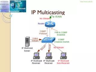
Layer 2 Multicast Protocols Multicast Table • Layer 2 switches have some degree of multicast awareness to avoid flooding multicasts to all switch ports. • The following are the two methods to control multicast at Layer 2 on multilayer switches: • IGMP snooping • Cisco Group Management Protocol (CGMP) Multicast Traffic: 1.5-Mbps IP multicast–based video feed sent from a corporate video server Sent only to those hosts that have joined that multicast group.
IGMP Snooping I have to examine every multicast packet to see if there are any join or leave requests. Whew! This is a lot of work! Multicast Table • IGMP snooping is an IP multicast constraining mechanism that examines Layer 2 and Layer 3 IP multicast information to maintain a Layer 2 multicast table. • IGMP snooping operates on multilayer switches, even switches that do not support Layer 3 routing. • IGMP snooping requires the LAN switch to examine, or “snoop,” the IGMP join and leave messages, sent between hosts and the first-hop multicast router. • The IGMP protocol transmits messages as IP multicast packets; as a result, switches cannot distinguish IGMP packets from normal IP multicast data at Layer 2. Multicast Traffic: 1.5-Mbps IP multicast–based video feed sent from a corporate video server Sent only to those hosts that have joined that multicast group.
IGMP Snooping I have to examine every multicast packet to see if there are any join or leave requests. Whew! This is a lot of work! Multicast Table • Therefore, a switch running IGMP snooping must examine every multicast data packet to determine whether it contains any pertinent IGMP control information. • If IGMP snooping is implemented on a low-end switch with a slow CPU, this could have a severe performance impact when data is transmitted at high rates. • The solution to this problem is to implement IGMP snooping with special ASICs that can perform IGMP snooping in hardware. • Without specialized ASICs for IGMP snooping to operate with hardware switching, CGMP is the preferable choice for low-end switches. Multicast Traffic: 1.5-Mbps IP multicast–based video feed sent from a corporate video server Sent only to those hosts that have joined that multicast group.
CGMP • CGMP (Cisco Group Management Protocol) : allows Catalyst switches to learn about the existence of multicast clients from Cisco routers and Layer 3 switches. • CGMP is based on a client/server model. • The router is considered a CGMP server, with the switch taking on the client role. • The basis of CGMP is that the IP multicast router sees all IGMP packets and, therefore, can inform the switch when specific hosts join or leave multicast groups. • The switch then uses this information to construct a forwarding table.
Multicast Packets CGMP • When the router sees an IGMP control packet, the router creates a CGMP packet. • This CGMP packet contains the request type (either join or leave), the multicast group address, and the actual MAC address of the client. • The packet is sent to a well-known address to which all switches listen. • Each switch then interprets the packet and creates the proper entries in a forwarding table. IGMP Join Request
CGMP • CGMP is a legacy multicast switching protocol. • All current-generation (and future) Catalyst switches support IGMP snooping. • IGMP snooping has several advantages over CGMP, such as the ability to operate without a first-hop router.
Protocols Used in Multicast • 2 types of multicast distribution trees • Source trees - shortest path tree (SPT) • Shared trees - rendezvous point (RP) between multicast sources and destination • 2 types of multicast routing protocols • Dense mode protocols : flood multicast traffic to all parts of the network and prune the flows where there are no receivers, using a periodic flood-and-prune mechanism. • Sparse mode protocols : use an explicit join mechanism where distribution trees are built on demand by explicit tree join messages sent by routers that have directly connected receivers
Reverse Path Forwarding (Rick) • Reverse path forwarding (RPF) is the mechanism that performs an incoming interface check to determine whether to forward or drop an incoming multicast frame. • RPF is a key concept in multicast forwarding. • This RPF check helps to guarantee that the distribution tree for multicast is loop-free. • In addition, RPF enables routers to correctly forward multicast traffic down the distribution tree.
Reverse Path Forwarding For traffic flowing down a source tree, the RPF check procedure works as follows: • The router looks up the source address in the unicast routing table to determine whether it arrived on the interface that is on the reverse path back to the source. • If the packet has arrived on the interface leading back to the source, the RPF check is successful and the router replicates and forwards the packet to the outgoing interfaces. • If the RPF check in the previous step fails, the router drops the packet and records the drop as an RPF failed drop.
RPF check fails 151.10.3.21 224.1.1.1 • The router in the figure receives a multicast packet from source 151.10.3.21 on interface S0. • A check of the unicast route table shows that this router uses interface S1 as the egress (exit) interface for forwarding unicast data to 151.10.3.21. • Because the packet instead arrived on interface S0, the packet fails the RPF check, and the router drops the packet.
RPF check succeeds 151.10.3.21 224.1.1.1 • With this example, the multicast packet arrives on interface S1. • The router checks the unicast routing table and finds that interface S1 is the correct ingress (incoming) interface. • The RPF check passes, and the router forwards the packet.
Non-RPF Traffic Do Not Forward • In multilayer switched networks where multiple routers connect to the same LAN segment, only one PIM-designated router forwards the multicast traffic from the source to the receivers on the outgoing interfaces. • Router A, the PIM-designated router (PIM DR), forwards data to VLAN 1 and VLAN 2. • Router B receives the forwarded multicast traffic on VLAN 1 and VLAN 2, and it drops this traffic because the multicast traffic fails the RPF check. (Source IP is via the other interface.) • Traffic that fails the RPF check is called non-RPF traffic. Source IP Address is not on these interfaces, but interface connected to Campus Network Router.
PIM Sparse-Dense-Mode • PIM sparse-dense mode : the recommended solution from Cisco for IP multicast. • PIM-DM : does not scale well and requires heavy router resources. • PIM-SM offers limited RP configuration options. • If no RP is discovered for the multicast group or none is manually configured, PIM sparse-dense mode operates in dense mode. Therefore, you should implement automatic RP discovery with PIM sparse-dense mode.
Automating Distribution of RP (FYI) • PIM-SM and PIM sparse-dense modes use various methods, discussed in this section, to automate the distribution of the RP. • This mechanism has the following benefits: • It eliminates the need to manually configure RP information in every router and switch in the network. • It is easy to use multiple RPs within a network to serve different group ranges. • It allows load-splitting among different RPs and allows the arrangement of RPs according to the location of group participants. • It avoids inconsistency; manual RP configurations may cause connectivity problems, if not configured properly. • PIM uses the following mechanisms to automate the distribution of the RP: • Auto-RP • Bootstrap router (BSR)
I’m the RP Mapping Agent, here are the group-to-RP mappings. (every 60 secs) Auto-RP I’m going to learn about group-to-RP mappings because I am a member of the 224.0.1.40 multicast group, Cisco-RP-discovery. • Auto-RP automates the distribution of group-to-RP mappings. • defines which multicast groups use which RP. • All routers in the PIM network learn about the active group-to-RP mapping from the RP mapping agent by automatically joining the Cisco-RP-discovery (224.0.1.40) multicast group. • The RP mapping agent is the router that sends the authoritative discovery packets that notify other routers which group-to-RP mapping to use (every 60 seconds). • Such a role is necessary in the event of conflicts (such as overlapping group-to-RP ranges).