Link Specification Group (LSG)
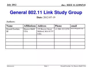
Link Specification Group (LSG). Agenda. General stuff (Jorgen) System requirements to optical link Long document, but short discussion (depends on you) Associated future projects A major planning/schedule milestone Role of LSG GTBX function and interface specification (Paulo)

Link Specification Group (LSG)
E N D
Presentation Transcript
Agenda • General stuff (Jorgen) • System requirements to optical link • Long document, but short discussion (depends on you) • Associated future projects • A major planning/schedule milestone • Role of LSG • GTBX function and interface specification (Paulo) • Major discussion point today based on document distributed. • Internal implementation not the subject !. • Status and results of testing of optoelectronics (Jan) slide 2
Functions needed • TTC: Trigger and timing control • Timing reference: clock(s), timing adjust , jitter, , ? • Trigger signals: trigger accept(s), trigger type, , , ? • Sync control signals: reset, calibration pulse injection, , , ? • Fixed and stabilized delay and latency (as short as possible) • Unidirectional: down • Number of signals needed ? • Handling multiple FE chips: simple fan-out ? • Reliability: Very high (SEU sensitive PIN/TIA in radiation !) • Controls/monitoring: ECS (Experiment Control System) • Control of parameters in front-ends (with readback) • Monitoring: temp, voltage, etc. • Also DSS related signals ? (very high reliability required, fail safe, etc.) • Effective data rate needed ? (normally not very high) • Bidirectional • Handling multiple FE chips: addressing, serial/parallel bus ?, other ? • Reliability: high • Readout • Readout of event data • Maximum data rate possible • Latency not an issue • Unidirectional: up • Handling data from multiple FE chips: Merging data streams or local event building • Serial or parallel connections ? • Reliability: high ( single bit flips in readout data can be accepted at low rate) • Trigger data • Similar to readout but constant (and short) latency may be required. slide 3
Link topology • Separate physical links for each function using same components. • Merge all into same physical link • Point to point. • Redundancy ? slide 4
System architecture • Decisions on the topology of the front-end link have significant effects on the global system architecture. slide 5
Fan-out on down link ? • Down link can relatively easy use optical fan-out • TTC information of fan-out nature • ECS information of low bandwidth • Each GBT just needs a few address bits (4). • “High” power laser in protected environment • But most likely still not low priced standard component • But is it really practical ? • High power non standard laser • Optical fan-out (not cheap either) • More complicated fiber routing • FPGA’s have bidirectional link interfaces Proposal: If it only requires a few address bits in GBT and no other design complications, then we can just as well put it in. Time will then show if it is really worth using/keeping it slide 6
Monitoring and control chip • External chip with basic monitoring and control functions • ID information (Efuses ?) • N ADC channels • M DAC channels • 8/16/32 PIO • JTAG, I2C, ? interface using PIO pins with protocol handling done by FPGA in off-detector part. • Specific power control functions ? • Detector safety system functions ?. • Very delicate as this is the last protection level of detectors and normally make fully independent from normal control/monitoring system !. • General specification to be outlined and discussed in LSG. slide 7
Non SLHC usage • Other users: • NA62 • ILC, CLIC: Too far out in the future ?. • Other: Panda, , , ,. • If well working link there, then I bet several HEP users will appear. • 40.08 MHz will not be the magic frequency • Integer clock ratios can relatively easily be handled • Basic clocking range: 20 – 40MHz (use of crystal !) • Power down of front-ends between spills. • No effect on GBT itself • Other features needed ?. slide 8
TTC system project • In counting house only • Distribution • Simple optical/electrical fan-out • PON bidirectional network • Controller • Partitioning slide 9
GBT Link Interface Board: GLIB project • Needed by first GBT users to test system prototypes based on GBT links. • Availability will help to convince users to adapt the GBT link for their systems. • Does not need high integration • 4-8-16-32 ? GBT links, • 1 TTC (FPGA serial link) • 1 ECS (Fast Ethernet), • 1 DAQ (Gigabit Ethernet) • Must be highly flexible • Supplied with basic firmware that works reliable • Allow users to modify firmware according to their needs • Needs to be well supported !. • Experience gained with this will be very valuable for designing final GBT/TTC/ECS/DAQ interface modules for final applications slide 10
Major decisions/milestones • 2008 • Design and prototyping of basic building blocks: TIA, laser driver, PLL, serializer, deserializer , • First tests of optoelectronics components (e.g. to understand SEU in PIN receivers) • Start link specification meetings • First version of a general link specification • 2009 • Design/prototype/test of basic serializer/deserializer chip • Use of such a design for Phase 1 upgrades will require major manpower and resources to put it in production: NRE, packaging, qualification, test, support, etc. • Design/prototype/test of optoelectronics packaging • Detailed link specification document • 2010 • Prototype of “complete” link interface chip • Final prototype of optoelectronics packaging • Major decision to take depending time schedule of LHC upgrades: • Put current version (4.8Gbits/s) in full scale production. • Jump to new technology to get ~10Gbits/s link • 2011: Option A • Extensive test and qualification of full link prototypes • System demonstrator(s) with use of full link • Final production version of optoelectronics and link interface chip(strong dependency on time schedule of LHC upgrade program) slide 11
Link Specification Group: LSG • Include other members ? • From experiments ? • Specific experts ? • Explicitly non CERN members ?. • Should not become too big. • Agree on initial version of GBTX specification document. • Regular meetings with presentations of project status (every ~6 months) • Invite potential users to present their needs ? • Other functions of this group ? • Identify collaborators ? • Identify first initial users ? • ? slide 12