Download
1 / 17
170 likes | 350 Views
Optical link specification ATLAS inputs. Upgraded tracker description Radiation constraints Strips modules and super-modules (staves) Data volume Pixels Strips GBT = Super-module controller Links Module Super-Module Data TTC DCS and operation constraints B-layer replacement.

E N D
Optical link specificationATLAS inputs Philippe Farthouat, CERN Upgraded tracker description Radiation constraints Strips modules and super-modules (staves) Data volume Pixels Strips GBT = Super-module controller Links Module Super-Module Data TTC DCS and operationconstraints B-layer replacement
Upgraded Tracker Strawman Layout • All silicon : pixels, short strips and long strips • Readout organisation in modules and staves
Radiation • Running up to 3000 fb-1 • Design for 6000 fb-1 • Shouldtake about 6 years (?) hadron rate For 3000 fb-1
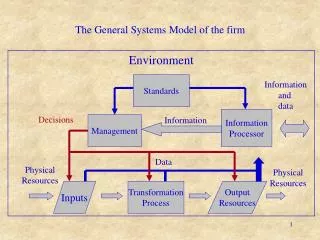
Module #1 Module #2 Module #10 Cooling In TTC, Data & DCS fibers Opto SMC DCS interlock DCS env. IN Cooling Out SMC Hybrid Service bus PS cable Strips modules and super-modules • ~1-m long per half-barrel • Short strips • 20 modules per half-barrel (single-sided) • 40 128-channel FEIC per module • 800 FEIC / super-module • Long strips • 38 modules per half-barrel (single-sided) • 10 128-channel FEIC per module • 380 FEIC / super-module
Pixels • Not muchdoneso far for defining modules etc. • Module size identical to current one • FEICs 4 times bigger than the current one • Pixel size is ½ the current one • One FEIC handles about 20,000 channels
Architecture of the readout • FEIC, module controller, super-module controller (GBT) 40 or 10 FEIC per module 20 or 40 Modules per super-module GBT
WorkingAssumptions • The read-out architecture should be as identical as possible for the strips and the pixels so that one can avoid extra design diversity and share as much as possible design efforts and costs. This common approach is to be applied from the front-end electronics up the off-detector electronics. In particular the Read-out Drivers (ROD) for the strip and pixel detectors are assumed to be identical (as they are in the current design) • The material budget is a key element for the upgraded tracker and hence the solutions which minimise the amount of material are always preferred • The radiation environment of the front-end electronics will be extremely harsh. In particular a high level of single event upsets can be expected. The read-out architecture should be kept as simple as possible and in particular complex tasks such as partial event building, data integrity check, etc. requiring extra buffers in the front-end should be avoided • The amount of services connected to the tracker should be kept as low as possible, not only to maintain an overall low material budget (the services located at large radius are less damaging to the calorimeter resolution) but also because the available volume for services routing is severely limited. This will also ease the installation process
Data volume • Assumptions • 100 kHz L1A rate • Couldbe more • Tracking not part of level-1 trigger • L1A latency up to 256 BC • Longer than the current one • Pixel • B-Layer 640 Mb/s per FEIC • Otherlayers 320 Mb/s per module
Data volume for strips • A super-module contains up to 20 such modules • 3.2 Gb/s effective data rate Number of bits for 40 FEIC Short strips 1.35 safety factor Withenoughderandomiser size 160 Mbits/s isappropriate for a short strip module From Tony Weidberg
Module #1 Module #2 Module #10 Cooling In TTC, Data & DCS fibers Opto SMC DCS interlock DCS env. IN Cooling Out SMC Hybrid Service bus PS cable GBT = Super-module controller • Links Module GBT • Data • TTC • DCS and operation constraints
Data link module controller GBT • 160 Mbits/s for the module controller to the GBT looks OK for strips • Not so large safety factor • Redundancy and commonalitywith the pixels ispointingtowards 320 Mbits/s • Left open for the time being • Up to 20 input data links @ 160 Mbits/s to the GBT
TTC links BGT Modules • The TTC links are used to transmit to the front-end: • A clock synchronised with the beam (either the LHC clock or a multiple of it) • The L1A • Fast commands such as the bunch counter reset (BCR) or the event counter reset (ECR) • Control data to be stored in the FEICs, MCs and SMCs (e.g. threshold, masks, …) • Slow commands allowing reading the contents of registers in the different ICs • Unidirectional links to minimise #lines • To read a register, command transmitted on TTC link, data transmitted on the read-out data link • TTC links bandwidth dictated by : • Clock frequency to be transmitted • Necessity to transmit simultaneously the L1A and other commands (e.g. Bunch Counter Reset [BCR]) • Necessity to transmit some information with the L1A (e.g. a trigger type) • Necessity of forward error correction to fight SEUs needed • Necessity of DC balanced codes and self clock recovery protocols necessary • Bandwidth greater than or equal to 80 Mbits/s
Data & TTC links module controller - GBT • Willing to minimise the size of the service bus and to simplify as much as possible the system • DC balanced codes necessary as long as the serial power option isalive • One 160 (or 320-MHz) clock differentially transmitted from the GBT to the Module Controller together with a differential data line able to carry 160 (or 320)-Mbits/s. • During a 25-ns period, 4 or 8 bits of information are transmitted (8 or 16 during a 50-ns period) • Only a fraction of them available because of DC balanced codes • One data read-out differential line transmitting read-out data at 160 (or 320)-Mbits/s from the MC to the SMC • This option requires at most 3 differential lines per read-out hybrid, i.e. 60 differential lines per super-module • The capability of sending a single clock to several MC to be considered in order to reduce the number of needed differential links
DCS and operationconstraints • Willing to power a super-modules in a verysafeway • Power the GBT and optocircuitry if local temperature OK • Check temperature of each module and power on or not • Easy if DC-DC • A mess with serial power • Interlock circuitry • DCS functionalityneededat the level of the GBT • Local temperature • Humidity • Inlet/outletcoolingtemperature • Local power (V, I) • Temperature of each module • ON/OFF power of each module • Interlock circuitry • When a module is on, DCS data fromthis module (additionaltemperature, V, I etc.) comingfrom the Module Controller and the FEIC • As part of the data • No wish to have a specialdedicatedlink for it
Simplistic block diagram • DCS couldbeintegrated or separated • FPGA at the receiving end • Not too exotic protocol • Optodevicesincluding the laser driver and the receiving amplifier shouldbeseparated • Might not belocatedat the same place as the GBT because of radiation constraints
B-Layer replacement: Intermediatestep? • Shouldhappen in 2012 • New FEIC development in 0.13 • Current architecture • Module optoboard • Parallelopticallink • Couldbereplaced by a GBT • Bandwidthrequirement ~1 Gb/s