Download
1 / 19
190 likes | 229 Views
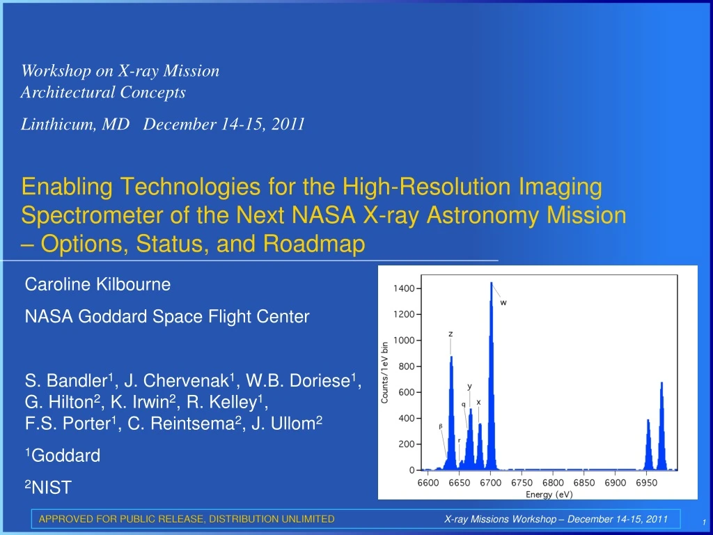
This presentation covers the options, status, and roadmap of enabling technologies for the high-resolution imaging spectrometer of the upcoming NASA X-ray astronomy mission. It discusses the importance of low-temperature detectors for achieving high resolution in imaging spectroscopy and explores leading technologies, multiplexed read-out methods, and the technology roadmap. Details on resistance-based thermistors, magnetically coupled calorimeters, transition-edge sensors, and inductive thermometers are provided, along with examples, performance metrics, and limitations. The significance of non-equilibrium signals in equilibrium devices for position discrimination is also discussed, along with insights into superconducting non-equilibrium detectors like microwave kinetic inductance detectors (MKIDs). Overall, the presentation emphasizes the need for continued investment in developing these cutting-edge technologies for advanced X-ray astronomy missions.

E N D
Enabling Technologies for the High-Resolution Imaging Spectrometer of the Next NASA X-ray Astronomy Mission – Options, Status, and Roadmap Caroline Kilbourne NASA Goddard Space Flight Center S. Bandler1, J. Chervenak1, W.B. Doriese1, G. Hilton2, K. Irwin2, R. Kelley1, F.S. Porter1, C. Reintsema2, J. Ullom2 1Goddard 2NIST
Outline • Why high-resolution detectors are low-temperature detectors • Leading technologies • Multiplexed read-out • Technology roadmap
High-resolution imaging spectroscopy requires low-temperature detectors Non-equilibrium: • Energy creates quantized excitations (E >> kT) • Number of excitations proportional to E • Fano-limited resolution • Low temperature required to avoid thermally generated excitations Equilibrium: • Sensor is in thermal equilibrium – DT proportional to DE/C • Resolution from accuracy of measuring DT on background of T fluctuations • Low-temperature neededto minimize thermal fluctuations and lower C ** For eV-scale resolution, T < ~ 0.1 K is required. **
Highest resolution demonstrated with equilibrium devices (microcalorimeters) • Thermometers can be based on: resistance, capacitance, inductance, paramagnetism, magnetic penetration, electron tunneling … • The leading technologies: • Resistance (semiconductor thermistors and resistive transition of superconductors) • Magnetically coupled calorimeters
Silicon thermistor-based calorimeter array for Astro-H • Base temperature of 50 mK • 36 pixels – silicon thermistors on 0.83 mm pitch with HgTe absorbers • Resolution at 6 keV ranges from 3.6 – 4.6 eV across EM and FM arrays • Lack of large-scale read-out technology limits arrays to a few hundred pixels • Further investment warranted if technique for multiplexing is demonstrated SXS FM candidate array
Transition-edge sensors (TES) – IXO/XMS baseline • Temperature and current dependence of the transition from the zero-resistance to normal-resistance state used for thermometry • XMS reference design based on GSFC TES design • Membrane-isolated Mo/Au TES with Tc ~ 90 mK, (base temperature at 50 mK) • Electroplated Bi/Au absorbers, 0.25 – 0.30 mm pitch • 1.8 eV resolution demonstrated, 2 – 3 eV routine in this design • Multiplexed SQUID read-out close to requirements for few-thousand pixel array • 32x32 arrays with microstrip leads successfully fabricated
TES – smaller pixels • Small pixels suited to shorter focal lengths and/or higher spatial resolution • In small TES devices, Tc depends sensitively on current – extends linear operating range of pixels • Don’t need membrane isolation; small size limits coupling to solid substrate • Heat sinking of solid substrate minimizes thermal crosstalk • Through choice of Tc, can be optimized for speed or resolution. 0.057 mm pixel with 0.03 ms time constant
TES – sub-eV resolution • TES on 0.075 mm pitch • Au absorber: 0.065 mm x 0.065 mm x 0.0045 mm • Design uses relatively slow pixels (1.6 ms decay times)
Inductive thermometers – using temperature dependence of paramagnetism or magnetic penetration of a superconductor • Arrays of Nb meanders with layer of magnetic material (Au:Er) or a low-Tc superconductor (Mo/Au) • change of magnetization measured as change of inductance • The Heidelberg group has achieved just better than 2.0 eV resolution at 6 keV with a Au:Er metallic magnetic calorimeter (MMC) • GSFC group recently obtained 2.3 eV resolution with Mo/Au magnetic penetration thermometer (MPT).
Magnetically coupled calorimeters (MCC) compared with TES • MCCs are intrinsically dissipationless • very large-format focal-plane arrays • MCC sensor material is electrically isolated • can be directly connected to metallic heat sink – simplifying reduction of thermal crosstalk • Dissipation in TES calorimeters allows electrothermal feedback • stabilizes operating temperature, relaxing temperature stability required at heat sink • TES read-out allows easy signal filtering, simplifying multiplexing. Each has advantages and disadvantages – parallel investment in both TES and MCCs is recommended
Using the non-equilibrium signal in equilibrium devices for position discrimination • Multiple absorbers connected thermally to the same thermometer via different thermal links • Demonstrated for TESs and MMCs • 2.6 eV resolution obtained in 9-pixel TES device with 0.065 mm pixels • Ideal “hydra” obtains somewhat worse resolution than for one big pixel of the same area due to thermal fluctuations between the absorbers
Superconducting Non-equilibrium Detectors • X-ray energy breaks Cooper pairs in a superconductor into quasiparticles. Microwave kinetic inductance detectors (MKIDs) are one technique for measuring the number of quasiparticles produced. • quasiparticles are trapped near sensitive element of a microwave resonator. • measure change in kinetic inductance from change in quasiparticle density • Intrinsic advantages: • speed of signal and high multiplexibility of MKIDs • Intrinsic disadvantages: • good energy resolution not demonstrated • competitive resolution at 6 keV not even theoretically possible with Nb • Not best match to IXO science; could be important for other experiments not requiring highest-resolution spectroscopy
Multiplexed read out: switched SQUID multiplexing • XMS reference design included time-division multiplexing (TDM) • Individual TES pixels are coupled (via each pixel’s SQUID) to a single amplifier • Multiplexed by sequential switching between SQUIDs • Used in TRL-4 TES read-out demo in 2008 (2.6 – 3.1 eV across 16 mux’d TESs) • Code Division Multiplexing (CDM) will soon reach TDM TRL level • All pixels ON all the time, polarity of coupling is switched • CDM has a sqrt(N) noise advantage over TDM, where N is the multiplexing scale • IXO/XMS noise budget extremely tight – CDM could provide important margin • CDM demonstrated: < 3 eV on 16 switched pixels using flux-matrixed CDM CDM TDM
Frequency domain multiplexing (FDM) • TES bias modulation • Different TES pixels AC-biased at different frequencies read out by single SQUID • X-ray pulses seen in amplitude modulation • Like CDM, pixels on all the time, imparting a sqrt(N) advantage over TDM • However, in identical pixels tested with AC and DC bias, significantly better resolution was obtained in the DC bias case, which may be fundamental • Microwave multiplexing • Pixel electronics form high-Q microwave resonant circuits (GHz scale), hundreds of which can be combined on a single coax • For MKIDs the sensor itself is part of the resonator • For TESs, MMCs, and MPTs, an unshunted rf SQUID is incorporated into the read out of each pixel, which is in turn coupled to a resonant circuit • Likely to be needed for pixel scales > ~10,000
Technology roadmap • SCOPE • Impossible to define a generic technology roadmap for new mission concepts that meet all or some of the original IXO scientific objectives. • Thus, we have kept close to the original XMS baseline for the detector system for the projected roadmap and cost, with an allowance for alternate technologies to merge into the flow. • Development of many of the alternate technologies is already funded for other applications. • The IXO/XMS roadmap is representative of the roadmaps needed for other LTD-based instruments • IXO/XMS TRL 4 reached in 2008 • The “2x8 demo” of multiplexed read-out of part of a TES array achieved the most fundamental goal of a demonstration of TRL 4 – basic technological components were integrated to establish that they will work together.
IXO/XMS roadmap – representative development path for a multi-component focal plane (from mid-TRL technologies) • TRL 5 demo of core array • Demonstrate multiplexed (3 columns x 32 rows) read-out of 96 different flight-like pixels … • work towards an Athena-scaled version (3x16) in progress now (Goddard/NIST) • TRL 5 demo of outer array • Demonstrate multiplexed (2 columns x 32 rows) read-out of 8x8 array of four-absorber devices… • TRL 5 of particle veto • Demonstrate particle veto prototype on scale appropriate for full XMS array… • integrated detector system TRL 5 • Demonstrate core array, outer array, and anti-coincidence detector together, though not in a flight-like arrangement.
IXO/XMS roadmap (3) • integrated detector system TRL 6 • Multiplexed (6x32) read-out of portion of full composite focal plane array • 128 different single-TES pixels in a 40x40 core array • 64 multi-absorber TES (256 0.6-mm pixels) of a full-sized outer array • Particle-veto integrated into the test set-up. • Electrical and thermal interconnects and staging approach flight-worthy design
Going forward • Cost to TRL 6 • Depends on mission goals and whether funding ramps up quickly or slowly. • Range ~$10M to $20M • first is for focused development of only the core-array technologies over ~4 years • latter is for slower development of something like full IXO/XMS detector system • some investment in technology variations, such as CDM • based on historical cost of advancing these technologies through APRA, Con-X development, and other sources. • Forecast • CDM could replace TDM in the roadmap in the next two years • In 2-4 years, new TES designs will enable improvements in intrinsic TES resolution • By 2017, magnetically coupled calorimeters and microwave multiplexing will be on solid footing, advancing towards mega-pixel arrays.