Download
1 / 45
450 likes | 468 Views
Learn about beam diagnostics and measurement techniques using fluorescent screens, Faraday cups, wall current monitors, beam transformers, and more at the John Adams Institute. Understand the crucial role of diagnostic equipment in accelerator science.

E N D
Lecture 13 -Beam Diagnostics Emmanuel Tsesmelis (CERN/Oxford) John Adams Institute for Accelerator Science 26 November 2009
Table of Contents I • Introduction • Observation of Beam & Measurement of Beam Current • Fluorescent Screen • Faraday Cup • Wall Current Monitor • Beam Transformer • Measurement Cavity • Determination of Beam Lifetime in Storage Ring • Measurement of Momentum and Energy of Particle Beam • Magnetic Spectrometer • Energy Measurement by Spin Depolarization
Table of Contents II • Measurement of Transverse Beam Position • Magnetic Beam Position Monitor • Monitor with 4 Electrodes • Measurement of Betatron Frequency and Tune • Measurement of Synchrotron Frequency • Measurement of Beam Optical Parameters • Dispersion • Beta Function • Chromaticity
Introduction • Beam circulating inside closed vacuum chamber is not visible from outside. • Access close to accelerator prohibited during operation. • Equip accelerator with wide range of measuring instruments - monitors • Establish whether there is beam in machine. • Measure physical parameters of machine. An accelerator is only as good as its diagnostic equipment.
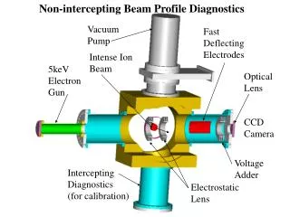
Fluorescent Screen • Applications • Measurement of beam position • Beam profile • Beam intensity • ZnS is effective fluorescent material • Mixed with sodium silicate, it is applied in thin layers onto glass, ceramic or metal. • Screens emit green light with high light yield. • Disadvantages • Limited use in high-vacuum environments. • Limited lifetime & burn out at beam spot after extendedexposure.
Fluorescent Screen • Thicker screens made of Al2O3 doped with chrome. • Predominantly red light. • High tolerance to beam exposure. • Low degassing rate and may be used in UHV. Left – fixed version at the end of linac. Right – movable screen which may be moved in/out of beam line.
Fluorescent Screen • Limitations • Non-linear relationship between light yield and beam intensity • Long afterglow • Several ms to seconds • Not possible to resolve time structure of beam (ns. range). • Read-out • Emitted light viewed using television (CCD) camera in control room. • CCDs are susceptible to radiation damage. • Protect by lead shielding and install at low radiation level locations.
Faraday Cup • Applications • Simplest method to measure beam current/intensity is to completely absorb beam in block of conducting material. • Measure captured charge by measuring resulting current. Faraday cup with coaxial structure • At high energies, penetration depth • is large – material block must be • very thick. • Large energy transfer to absorber – • strong heating. • Multiple scattering – transverse • broadening of beam -> particle losses • Secondary particle production by pair • production. • Therefore, Faraday cup restricted to • low-energy beam applications.
Faraday Cup • Measurement of time structure • Achieve very high bandwidth of many GHz. • Prerequisite for high bandwidth is consistent coaxial structure in which ratio of diameter D of outer conductor to diameter d of inner conductor and the impedance remains constant from cup beginning to read-out electronics.
Wall Current Monitor • Cyclic Accelerator • Need to measure the current without disturbing the beam • Current • Outside vacuum tube • Within vacuum tube • There is a wall current Iwall flowing in vacuum chamber Lay-out of wall current monitor Ibeam = -Iwall
Wall Current Monitor • Beam current determined by measuring current in vacuum chamber wall. • Measure voltage V developed over ohmic resistance R (~ 1 Ω) across a ceramic gap. • Large number of resistors are used, connected in parallel around the vacuum chamber • Wall current monitor can achieve very high bandwidths (several GHz).
Beam Transformer Ideal iron core around particle beam This arrangement acts like a transformer: Primary winding – particle beam Secondary winding – inductive coil Beam Transformer Equivalent circuit of beam transformer
Beam transformer output (secondary) voltage Uout CTRT long compared to duration of bunch pulses Secondary voltage becomes: Time dependence of output voltage Uoutis only roughly proportional to beam current Ibeam(t). True for relatively long bunches with limited frequency components For short bunches Uout is considerably longer than the current pulse. Area under voltage pulse can be used as good approximation of number of particles. Beam Transformer
Current Measurement Cavity • Beam accelerated by high-frequency field has periodic time structure with beam current. • As beam passes along axis of resonant cavity, accompanying electric field generates high-frequency wave. • Corresponds to resonant excitation of electric oscillator by periodic current. • In order to determine current, field energy must be extracted from cavity and measured electronically. Cavity for measuring beam current Electrical behaviour described by equivalent circuit
Capacitive Coupling Antenna Signal is carried via coaxial cable to terminating resistance Additional coupling capacitance Cc and real load resistance Rc Coupled signal can be rectified using a diode (non-linear behaviour) and then directly measured. Calibrate using Faraday cup for absolute measurements Current Measurement Cavity Signal extraction from measurement cavity using capacitive coupling antenna
Beam Lifetime in Storage Ring • Beam circulating in storage ring decays in intensity due to: • Collisions with residual gas molecules. • Occasional large energy losses through synchrotron radiation (for electrons). • Non-linear resonances Time dependence of beam current and lifetime
Decline in intensity has exponential form with τbeambeing the beam lifetime: Lifetime is not constant during machine operation. Lifetime relatively short at beginning (when intensity is high) because intense synchrotron radiation (for electron beams) causes high level of gas desorption on vacuum chamber surface reducing vacuum pressure. As beam current decreases, vacuum improves and lifetime increases. Beam Lifetime in Storage Ring dI(t)/dt = - I0/beam exp(-t/beam) = I(t)/beam
Beam Lifetime in Storage Ring • Using a current monitor, the current is continuously monitored, with measurements repeated at frequent intervals. • Since beam lifetime can vary from few seconds to many hours (depending on operating conditions), it is useful to vary the time interval between measurements. • Short lifetimes – beam current varies rapidly & only few measurements required for reliable lifetime measurement short time interval. • Long lifetimes – individual current measurements must last sufficiently long for statistical fluctuations not to cause large errors in lifetime measurement.
Measurement of Momentum & Energy • Measure angle of deflection in known B-field. Deflection of a charged particle in a magnetic field. Magnetic spectrometer to measure particle momentum & energy
Measurement Parameters Incoming beam angle must be precisely defined. Fix beam position using precisely aligned screens Measure bending angle after deflection using fluorescent screen. ∫Bz required, which is obtained by measurement of the B-field as a function of coil current. Watch out for hysteresis of iron magnets! Cyclic Accelerators Total bending angle of all dipole magnets must be 2π. Connect additional dipole in series with accelerator dipoles and install precise field gauge within it – e.g. NMR probe. Field and energy continuously monitored. ΔE/E ~ 2 10-4. Measurement of Momentum & Energy
Polarization Effect Electrons injected into a storage ring have spins uniformly distributed in all directions unpolarized. As they circulate, they precess in vertical field of bending magnets. Electrons spins eventually align themselves anti-parallel to B-field as a result of emitting synchrotron radiation polarized. Quadrupole and higher multipole magnets acting on beam can disturb spins. Depolarization over time τD Want τD > τp Polarization P < 94% Energy Measurement - Spin Polarization
Perturb polarization using weak transverse magnetic field which oscillates rapidly at precise frequency (fast kicker magnet). Angle of precession increases with each revolution in resonant fashion until it is perpendicular to direction of dipole field polarization vanishes. α = ½ (g-2) = 1.159652193 10-3 being the electron anomalous magnetic moment. Change the frequency of the transverse perturbing kicker field in small steps, observing the variation of polarization level. Polarimeter Compton backscattering Unpolarized – symmetric X-ray photon rate. Polarized – asymmetric X-ray photon rate. Energy Measurement - Spin Polarization
Require centre of beam to always lie as close as possible to ideal orbit. Defined by quadrupole axes. Transverse deviation of circulating beam from orbit must be less than 100-150 μm. Measure transverse position of beam at as many points around the accelerator and implement corrective measures. Transverse Beam Position
Measure B-field due to beam and so avoid particle losses. The difference in signals from the two opposite coils within each pair provides measure of beam position in that plane. In order to measure postion in both planes simultaneously, install 4 coils arranged at 90o intervals around transformer coil. Magnetic Beam Position Monitor Magnetic beam position monitor
Consists of 4 electrodes (electrical pick-ups) arranged symmetrically around beam axis coupling to E-field. Electrodes tilted away from beam axis by 45o in order to reduce amount of synchrotron radiation hitting them directly. Monitor with Four Electrodes Beam position monitor with four electrodes
Monitor with Four Electrodes • If beam lies exactly in middle of monitors, ideally all signals will have same intensity. • But there are variations in signal sizes – • Electrode tolerance • Vacuum chamber geometry • Cables and electronics which follow for read-out • If signal has intensity Io + ΔI, will then have position error of • For a = 35 mm and want Δxerror< 0.1 mm then the relative error in an electrode signal may not larger than
Monitor with Four Electrodes • Fundamentally, it is not possible to define with arbitrary precision the point relative to which the beam position is being measured. • Monitor connected to vacuum chamber, which is generally fixed to magnets. • Magnets positioned with tolerance of ±0.2 mm • Alignment errors of quadrupoles also create orbit distortions. • Even if beam position adjusted so that it has no offset in any of the monitors, this will not necessarily correspond to real ideal orbit.
E-field component along beam direction is zero, i.e. in centre of cavity. If beam lies exactly along orbit, then its field cannot induce any oscillation in resonator no output signal TM210 mode in rectangular cavity Position Measurement with Resonant Cavity Rectangular cavity in TM210 mode E-field Ez parallel to beam axis for TM210
Away from the beam axis the field increases, with opposing sign on either side. Oscillating signal is coupled out using short capacitive coupling antenna. Amplitude and phase measured using phase detector. Position Measurement with Resonant Cavity a=141 mm B=71 mm L= 50 mm For TM210, resonant frequency is 2.998 GHz (S-band linac)
Betatron Frequency & Tune • Once set of beam optics has been installed, the working point – tune Q – must be measured to check that it lies far enough away from strong optical resonances. • Tune Q = q + a • q = integer • 0 ≤ a ≤ 1 • Measuring tune also allows detection of changes in focusing. • B-field imperfection • Space charge effect • Use the tune to monitor stability of the beam focusing during machine operation. • Amounts to measuring frequency of transverse beam oscillations.
Betatron Frequency and Tune • The solution of the oscillation equation (assuming very weak damping from synchrotron radiation) • Measurement • Fractional tune a • If beam undergoes betatron oscillations, measure Ω with fast position monitor since revolution frequency is fixed. • Integer tune q • Difference between reference orbit and standing betatron oscillation about reference orbit caused by altering steering coil strength.
Betatron Frequency & Tune • Excite beam into coherent transverse oscillations. • Fast bending magnet (10-4 Tm) which produces periodic field B(t) = B0 sin ωgen t • Equation of forced motion • As damping is very weak, resonance occurs if ωgen = Ω A fast kicker magnet stimulates beam at frequency ωgen, which is varied until resonance is found. Amplitude of induced betatron oscillation measured using fast position monitor
Synchrotron Frequency • Phase-modulated RF voltage excites longitudinal oscillations • If modulating frequency lies sufficiently close to synchrotron frequency • Phase-modulated signal read-out by electrode or measuring cavity. Oscillations are excited by phase modulation of the generator and measured using a phase detector which obtains signal from electrode or measuring cavity
Synchrotron Frequency • Demodulation performed by phase detector. • Frequency of signal generator varied until resonance of phase oscillation is found • This yields synchrotron frequency directly • High-frequency signal supplied by master generator is modulated with tunable frequency ωmodusing electronic phase shifter. • Periodic modulation signal comes from signal generator whose frequency is measured by meter.
Beam Optical Parameters - Dispersion • Determined from position measurements at several points around the orbit. • Vary momentum p of particles by Δp while keeping magnet strengths constant. • Beam position shifts distance Δx(s) = D(s) Δp/p onto dispersive trajectory. • Dispersion is
Beam Optical Parameters - Dispersion • Change frequency RFof accelerating voltage by Δ. • Since phase focusing means the harmonic number remains constant, circumference of particle trajectory changes and hence no longer matches orbit. • Stable particle path shifts onto dispersive trajectory corresponding change of momentum Δp
Beam Optical Parameters – βFunction • If strength of quadrupole changes by amount Δk, tune of cyclic machine shifts by • The size of shift is proportional to value of βfunction in quadrupole. • Assuming k is constant along quadrupole axis and variation of βfunction is small in quadrupole • Start from particular set-up of beam optics and impose well-defined change in quadrupole strength Δk • By measuring tune Q before & after change the average βfunction in quadrupole is
Beam Optical Parameters - Chromaticity • Chromaticity measurement essential for correct tuning of sextupoles. • Vary the momentum of circulating particles and measure tune Q before and after change • Momentum varied by changing RF frequency. • Relationship between change in momentum and tune is far from linear. • Measure function ΔQ(Δp/p) whose value in the region around nominal value yields chromaticity.