Download
1 / 25
250 likes | 472 Views
Modular Electronics the past, the present and the future. Markus Joos CERN. The past: NIM The present: PCI and PCIe SHB Express The future: Serial interconnects VXS ATCA μ TCA. NIM basics. Initially: NIM = Nuclear Instrument Modules But it was used outside of "nuclear science"

E N D
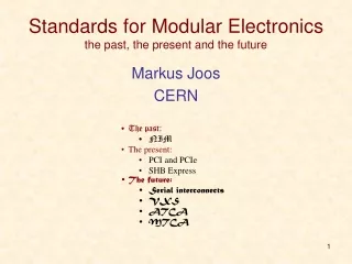
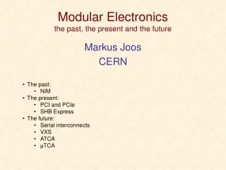
Modular Electronicsthe past, the present and the future Markus Joos CERN • The past: • NIM • The present: • PCI and PCIe • SHB Express • The future: • Serial interconnects • VXS • ATCA • μTCA
NIM basics • Initially: NIM = Nuclear Instrument Modules • But it was used outside of "nuclear science" • Therefore: NIM = National Instrument Modules • But is was used outside of the USA • Therefore: NIM stands for NIM • 1st NIM standard: July 1964 • 1st commercial module: November 1964 • Module dimensions: 34 x 221 x 246 mm • NIM logic levels: • 0 = 0A (0V) • 1 = -12 to -32 (typical -16) mA at 50 Ω (-0.8V) • NIM connector • 42 pins in total • 11 pins used for power • 2 logic pins (reset & gate) • pin 1 & 2 = +/- 3V (claimed by Wikipedia) • 29 reserved / spare pins • 1983 NIM digital bus (IEEE 488 – GPIB) • Rarely used
NIM – the next generation • NIM is still very alive • General purpose NIM module with programmable logic (LabView, USB) • 16 Channel 12 bit 5 GS/s Flash ADC Waveform Digitizer with USB 2.0 read-out
bussed lines Initiator & arbiter Initiator Target Target arbitration PCI basics • PCI (Peripheral Component Interconnect): first standardized in 1991 • Initially intended for PC cards • Later spin-offs: CompactPCI, PXI, PMC • Main features • Synchronous timing • But wait cycles possible • Clock rates • Initially 33 MHz. Later: 66 MHz, (PCI-X: 100 and 133 MHz) • Bus width • Initially 32 bit. Later: 64 bit • Signaling voltage • Initially 5 V. Later 3.3 V (->slot keying) • Terminology • A data transfer takes place between an INITIATOR (master) and a TARGET (slave) • Bus topology • 1 to 8 (depending on clock rate) slots per bus • Busses can be connected to form a tree • Address and data as well as most protocol lines are shared by all devices; The lines used for arbitration are connected point-to-point; The routing of the interrupt request lines is more complicated… • A system can consist of several Initiators and Targets but only one Initiator can receive interrupts
PCI basics - 2 • Address spaces • Configuration space • Standardized registers for the dynamic configuration of the H/W (plug-and play) • I/O space • For device specific registers • MEM space • General purpose space for registers and memory • Cycle types(encoded in the C/BE[3::0]# lines) • Single cycles • Read / write of all 3 address spaces • Bursts • MEM read / write (with special features for cache handling) • (Typical) performance • Single cycle: 2 (3 for read) -> ~10 clock cycles • 33 MHz / 32 bit: 66 MB/s -> ~10 MB/s • 64 MHz / 64 bit: 264 MB/s -> ~40 MB/s • Bursts: • 33 MHz / 32 bit: Max. 132 MB/s • 64 MHz / 64 bit: Max. 528 MB/s • PCI-X @ 133 MHz: 1.06 GB/s • PCI-PCI bridges add additional delays
PCI devices under Linux Show PCI tree: lspci -t -v -[0000:00]-+-00.0 Intel Corporation E7520 Memory Controller Hub +-00.1 Intel Corporation E7525/E7520 Error Reporting Registers +-01.0 Intel Corporation E7520 DMA Controller +-02.0-[0000:01-03]--+-00.0-[0000:02]----03.0 CERN/ECP/EDU Unknown device 0144 | +-00.1 Intel Corporation 6700/6702PXH I/OxAPIC Interrupt Controller A | +-00.2-[0000:03]----01.0 CERN/ECP/EDU Unknown device 0144 | \-00.3 Intel Corporation 6700PXH I/OxAPIC Interrupt Controller B +-04.0-[0000:04]----00.0 Broadcom Corporation NetXtreme BCM5721 Gigabit Ethernet PCI Express +-05.0-[0000:05]----00.0 Broadcom Corporation NetXtreme BCM5721 Gigabit Ethernet PCI Express +-06.0-[0000:06-08]----00.0-[0000:07-08]--+-04.0 Broadcom Corporation NetXtreme BCM5714 Gigabit Ethernet | +-04.1 Broadcom Corporation NetXtreme BCM5714 Gigabit Ethernet | \-08.0-[0000:08]--+-06.0 Broadcom Corporation NetXtreme BCM5704 Gigabit Ethernet | \-06.1 Broadcom Corporation NetXtreme BCM5704 Gigabit Ethernet +-07.0-[0000:09-0b]--+-00.0-[0000:0a]----02.0 CERN/ECP/EDU Unknown device 0144 | +-00.1 Intel Corporation 6700/6702PXH I/OxAPIC Interrupt Controller A | +-00.2-[0000:0b]----01.0 CERN/ECP/EDU Unknown device 0144 | \-00.3 Intel Corporation 6700PXH I/OxAPIC Interrupt Controller B +-1d.0 Intel Corporation 82801EB/ER (ICH5/ICH5R) USB UHCI Controller #1 +-1d.1 Intel Corporation 82801EB/ER (ICH5/ICH5R) USB UHCI Controller #2 +-1d.2 Intel Corporation 82801EB/ER (ICH5/ICH5R) USB UHCI Controller #3 +-1d.3 Intel Corporation 82801EB/ER (ICH5/ICH5R) USB UHCI Controller #4 +-1d.7 Intel Corporation 82801EB/ER (ICH5/ICH5R) USB2 EHCI Controller +-1e.0-[0000:0c]----01.0 ATI Technologies Inc Rage XL +-1f.0 Intel Corporation 82801EB/ER (ICH5/ICH5R) LPC Interface Bridge \-1f.3 Intel Corporation 82801EB/ER (ICH5/ICH5R) SMBus Controller The command “lspci” displays information about the PCI devices of a computer Show device details: lspci -v -s 02:03.0 02:03.0 Co-processor: CERN/ECP/EDU Unknown device 0144 (rev ac) Subsystem: Unknown device 2151:1087 Flags: bus master, 66MHz, medium devsel, latency 32, IRQ 209 Memory at d7200000 (32-bit, non-prefetchable) [size=512] I/O ports at 2000 [size=256] Memory at d8000000 (32-bit, non-prefetchable) [size=16M] Capabilities: <access denied>
Address PCI protocol Example: Single cycle read CLOCK 9 1 FRAME# 6 A/D Data 2 4 C/BE# BUS CMD BE#’s 10 3 IRDY# 7 TRDY# 8 5 DEVSEL# Data phase Address phase • The Target does not yet drive TRDY (it may need time to prepare the data) but asks the Initiator to wait • The Target has the data ready on the AD lines. The Initiator fetches the data in the same clock cycle • By de-asserting FRAME the Initiator tells to the Target that it does not want additional data after the next data word • The cycle is over and the protocol lines get released • Assertion of FRAME starts cycle • Initiator puts address and command (cycle type) on the bus • The Initiator signals that it is ready to receive data • The initiator uses the C/BE lines to define which bytes it wants to read • Target looks at the Address and drives DEVSEL if it was addressed. If no target drives DEVSEL after at most 6 clock the Initiator will abort the cycle • The ownership of the AD lines changes from Initiator to target (only for read cycles). This requires one clock cycle Color code: Initiator – Target - shared “#” indicates active low signals
PCIe (aka PCI Express) • Not a bus any more but a point-to-point link • Data not transferred on parallel lines but on one or several serial lanes • Lane: One pair of LVDS lines per direction (4 wires) • Clock rate: 2.5 GHz (PCIe2.0: 5 GHz, PCIe 3.0: 10 GHz) • 8b/10b encoding • 250 MB/s (PCIe 1.0) raw transfer rate per lane • Devices can support up to 32 lanes • Protocol at the link layer has nothing to do with protocol of parallel PCI • Fully transparent at the S/W layer
Some examples of PCI H/W 32 bit slot with 5V key 64bit slot with 3.3V key 6U CompactPCI chassis and card PC motherboard with PCI slots PXI system PMC card and carrier (VMEbus)
serial link Parallel bus -> Serial link Parallel Buses Are Dead!(RT magazine, 2006) • What is wrong about “parallel”? • You need lots of pins on the chips and wires on the PCBs • The skew on the data lines limits the maximum speed • Speed is a function of the length (impedance) of the lines • What is wrong about “bus”? • Communication is limited to one master/slave pair at a time (no scalability) • The handshake may slow down the maximum speed • All parallel buses are dead. All? No! • There is lots of legacy equipment • VMEbus is still used heavily (military / research) • PCs still support parallel PCI (but this will change) • What next? • Switched serial interconnects
Dev. Dev. Dev. Dev. Dev. Dev. Switch Dev. Dev. Mesh Star Serial links • Standards (just the most important) • PCIe • 1 / 10 GB Ethernet • Serial RapidIO • Infiniband • Serial ATA • FiberChannel • ……. • Commonalities • Signal rate: 2.5 – 10 GHz • Packet switching • Topology • Star: Device connects to a fabric switch • Dual Star: Device connects to two fabric switches (redundancy) • Mesh: All devices have direct links to all others • Differences • Support for interrupts • Support for programmed I/O • Quality of service (guaranteed bandwidth)
PICMG 1.3 – SHB Express • The SHB • Two (A & B) or 4 (A, B, C & D) connectors • Connector A: PCIe • (1 x16) or (2 x8) or (1 x8 + 2 x4) or (4 x4) • Connector B: PCIe • (1 x4) or (4 x1) • Connector C: • Additional I/O • Connector D: • 1 32bit PCI(-X) • SHBExpress = System Host Board standard for PCIe • Standardized in 2005 • Defined in the standard • SHB board mechanics (two board formats) • Interface between SHB and backplane • Additional I/O (SATA, USB, Ethernet, etc.) that may be routed to the backplane • Backplane design rules • Systems consist of: • One SHB • One backplane • One or several PCIe, PCI-X or PCI cards D C B A
SHB – the backplanes The backplane has to match the PCIe configuration of the SHB • x16 on connector A: graphics class • 2 x8 on Connector A: server class Segmented backplane with 4 SHB and 12 PCIe slots for a 19” 4U chassis SHB slot PCIe slots PCI(-X) slots A complete 4U system PCIe switch PCI bridge
The next generation What new standards are available? • VITA41: VXS • PICMG 3.x: ATCA (Advanced Telecommunications Computing Architecture) • PICMG MTCA.x: MicroTCA/uTCA • PICMG AMC.x: Advanced Mezzanine Card (for ATCA and uTCA) • Not covered in this talk: • VITA46: VPX • PICMG 2.x: Compact PCI (cPCI) • PICMG EXP.0: PCIe for cPCI • PCIMG CPLUS.0: A bit like EXP.0 • PICMG ATCA300.0: ATCA for 300mm deep systems (no rear I/O) • And many more…
VXS (VITA 41, ~100 pages) • Essentially 6U (but 9U not excluded) VMEbus with a new P0 connector • Two types of cards • Payload • Switch (one card required, second for redundancy) • Network topology: (dual) star • Connectivity for payload cards • 16 differential pairs (10 GHz) defined by the standard (and routed to switch cards) • 31 reserved pins available on P0 • Sub-standards • 41.1: Infiniband • 41.2: Serial RapidIO • 41.3 (draft): IEEE Std 802.3 (1000 Mb/s Ethernet) • 41.4 (draft): PCIe • Hot Swap: According to VITA 1.4 • System management based on I2C / IPMI but only formulated as recommendation
Advanced TCA (650 pages + IPMI) • More of a system than a board standard • Started in 2001 by ~100 companies • One form factor • Front: 8U x 280 mm x 30.48 mm (14 slots per 19” crate) • Rear: 8U x 60 mm (5W) • Supply voltage: -48 V (-> DC-DC conversion each on-board) • Power limit: 200 W (400 W) per card • Connectors • Zone 1: One connector for power & system management • Zone 2: One to five ZD connectors for data transfer • Zone 3: User defined connector for rear I/O • Connectivity • Up to 200 differential pairs • 4 groups • 64 pairs for Base Interface (usually Eth., star topology) • 120 pairs for Fabric Interface (star or full mesh) • Ethernet, PCIe, Infiniband, serial RapidIO, StarFabric • 6 pairs for Clock Synchronization • 10 pairs for Update Channel • System management based on IPMI, I2C and FRU data Zone3 Zone2 Zone1
ATCA HA features (applies also largely to μTCA) • Redundancy • Power Supply modules • Ventilators • Shelf managers • Switch blades • Electronic Keying • Based on FRU information payload cards may be accepted / rejected in a given slot • Hot swap • Payload board will only receive (payload) power if the shelf manager can guaranty for the availability of the required resources (power, cooling, signal connections) • Monitoring • Low level: IPMI on I2C • High level: SNMP (Simple Network Management Protocol) and other protocols on top of TCP/IP • System event logs • Cooling • Dynamically controlled fans and several alarm levels
Some ATCA equipment Shelves AMC Carriers Shelf manager(s) Backplane: Dual star Cutaway carrier (for full-size AMCs) RTM Hot-swap fans
AMC • Originally intended as hot-swappable mezzanine standard for ATCA but soon used as the basis for the μTCA standard • 6 form factors: • 74 or 149 mm wide • 13, 18 or 28 mm high • 180 mm deep • Power supply: 80W (max) on +12V (and 0.5W on 3.3V management power) • Connector: 85 pin (single sided) or 170 pin (double sided) edge connector • Connectivity • Up to 12.5 Gb/s • 20+20 LVDS signal pairs for data transfer (Eth, PCIe, SAS/SATA, RapidIO) • Clock interface, JTAG, I2C (IPMI)
μTCA • A system standard based on the AMC, standardized in 2006 • Min. signaling speed: 3.125 GHz • Connectivity: • 4 AMC LVDS pairs defined as “Common Options” (2 Eth. & 2 SAS ports) and connect to 1 or 2 MCH boards which provide the switching • 8 AMC LVDS pairs defined as (extended) fat pipes (1 or 10 G Eth, PCIe, RapidI/O). Connection to MCH not standardized • Remaining 8 LVDS pairs not defined (can be used for rear I/O (but rear I/O not foreseen in uTCA standard)) • System management based on IPMI / I2C • Hot-swap support for PSU & cooling • Redundant MCH (μTCA Controller Hub) • The MCH connector supports up to 84 differential pairs. Therefore only 7 pairs per AMC (based on a 12-slot backplane) can be routed to the switch.
Some uTCA products • 2U / 19” chassis • Slots for up to 12 AMCs • Cooling dimensioned for 40W per slot • 19” rack mountable • Dual star backplane • Up to 10 AMCs • External AC->DC PSU required • MCH • Fat-pipe mezzanines for: • PCIe • 10GB-Eth • Serial RapidIO • Clocks • 19” rack mountable • 8 full size and 4 compact size AMC slots • For 3rd party power supply modules • 6 mid size (single or double width) AMCs • AC or DC PSU • Single star backplane
xTCA degrees of freedom (not necessarily a complete list) • ATCA • Communication protocol(s) on the fabric channels • Routing of the fabric channels on the backplane (network topology) • Connection between front board and RTM • Degree of redundancy • Power supply at shelf level (230 VAC or -48 VDC) • AMC • Card height (13, 18 & 28 mm) • Card width (74 & 149 mm) • Communication protocols (currently 4 options) • Number of pins on the connector (85 or 170) • JTAG support • uTCA • AMC height & width • Degree of redundancy (MCH, PSU, cooling) • Routing of the fabric channels on the backplane • JTAG support • Connectivity of MCH to backplane (1 to 4 tongues) and type of communication protocol on the fat pipes
xTCA issues • The operation of an xTCA system requires a complex, standard compliant S/W infrastructure • Efforts to provide open source management S/W for xTCA: OpenSAF, SAForum • As many features of the standard(s) are optional, products from different vendors may not be compatible • Efforts to insure interoperability of xTCA products: CP-TA, SCOPE alliance • Many vendors seem to be in favour of “profiles” that limit the number of options given by the standards • ATCA profile for telecommunication • Proposal for a “physics profile” for xTCA under the umbrella of PICMG-US • The market does not yet provide lots of front end modules for physics DAQ • There is little information available about the system performance (end to end H/W performance and S/W overhead) of the data transfer links
What is the right standard for me? • This obviously depends on your requirements • Bandwidth & latency • Availability of commercial products (front end) • Existing infrastructure (S/W and H/W) and expertise in your experiment • Start and duration of the experiment • Scalability requirements • Trends in HEP • LHC & experiments @ CERN: VMEbus & PCI based • CMS: Calorimeter trigger prototype in μTCA • ATLAS: lAr ROD prototype in ATCA • LHC: prototype time distribution system in μTCA • COMPASS @ CERN: VXS derivative • XFEL @ DESY: control system in μTCA
Infiniband • Developed by Compaq, IBM, Hewlett-Packard, Intel, Microsoft and Sun from 1999 onwards • Characteristics • Bi-directional serial link • Aggregation of links (4x, 12x possible) • Link speed: 2.5, 5, 10 GHz • Special features • Data transfer performed without involvement of OS (latency < 2 μs) • Remote DMA (fetch data from the memory of a remote system) • Main purpose • Server and storage interconnect for high performance computing • Relevance for DAQ • Limited for a lack of DAQ products Serial Rapid I/O • Developed by Mercury Computer Systems and Motorola from 1997 onwards • Characteristics • Bi-directional serial link • Aggregation of links (2x, 4x, 8x, 16x possible) • Link speed: 1.25, 2.5, 3.125, 5, 6.25 GHz • Special features • Quality of Service (transfer requests can be prioritized) • Multicast • Main purpose • Chip/chip and board/board communication • Relevance for DAQ • Limited for a lack of DAQ products but some AMC/ATCA products