Download
1 / 42
420 likes | 440 Views
Explore the evolution of modular electronics standards from NIM to VMEbus, understanding the past, present, and future trends. Discover benefits of modularization and standardized interfaces in electronic systems.

E N D
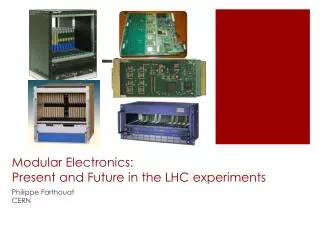
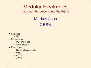
Standards for Modular Electronicsthe past, the present and the future Markus Joos CERN • The past: • NIM • The present: • PCI and PCIe • SHB Express • The future: • Serial interconnects • VXS • ATCA • μTCA
Why Modular Electronics? • As in programming a system becomes unmanageable if too much functionality is put into a single functional block • Modularizing DAQ electronics helps in these respects: • Allows for the re-use of generic modules in different applications • Limiting the complexity of individual modules increases their reliability and maintainability • You can profit from 3rd party support for common modules • Makes it easier to achieve scaleable designs • Upgrades (for performance or functionality) are less difficult • Etc. Why use Standards? • Benefit from 3rd party products, services and support • Competition gives you better prices and alternative suppliers • Standards make it easier to define interfaces between sub-systems • But not all standards are equally good: • Too old: poor performance, few suppliers, expensive • Too new: Interoperability issues, unclear long term support • Too exotic: Too few suppliers (sometimes just one)
NIM NIM crate • NIM modules (usually) • Need no software • Are not connected to a computer • Are used to implement trigger logic • These functions (any many others) are available • Discriminators • Coincidences • Amplifiers • Timers • Logic gates (and / or) • Level converters • HV power supplies • .... A small DAQ system
NIM basics • 1st NIM standard: July 1964 • 1st commercial module: November 1964 • Module dimensions: 34 x 221 x 246 mm • NIM logic levels: • 0 = 0A (0V) • 1 = -12 to -32 (typical -16) mA at 50 Ω (-0.8V) • NIM connector • 42 pins in total • 11 pins used for power (+/- 6, 12, 24V) • 2 logic pins (reset & gate) • 29 pins reserved since 1964 • 1983 NIM digital bus (IEEE 488 – GPIB) • Rarely used NIM connector
NIM – the next generation NIM is still very alive Some examples General purpose NIM module with programmable logic (LabView) 100 MS/s digitizer with optical read-out
VMEbus • (Complex) DAQ systems usually require custom built electronics modules which have to be: • Housed • Powered • Configured • Read out • VMEbus has traditionally been the technology of choice in many HEPexperiments and accelerator control systems because it offers features such as: • A well proven open standard that includes mechanical, electrical and protocol sections • Suitable card sizes • A data transfer protocol that is relatively easy to implement • An “ecosystem” of third party products (crates, processors, I/O modules, etc.) which are supported by the manufacturers for long durations • Currently there are more than 1000 VMEbus systems at CERN (accelerator & experiments)
VMEbus in action Examples of VMEbus systems in ATLAS In total there are about ~150 crates in ATLAS
VMEbus basics • Classes of modules (logical) • Master • A module that can initiate data transfers • Slave • A module that responds to a master • Interrupter • A module that can send an interrupt (usually a slave) • Interrupt handler • A module that can receive (and handle) interrupts (usually a Single Board Computer) • Arbiter • Electrical properties: TTL • Low = 0 ... 0.6 V • High = 2.4 ... 5 V • Protocol • Asynchronous with 4-edge handshaking • The duration of a VMEbus cycle depends on the speed of the master and the slave • Big endian byte ordering
VMEbus basics (2) • Main types of data transfers • Single cycles • Transfer 8, 16 or 32 bits of data (typically) under the control of the CPU on the master • Mnemonic: D8, D16 and D32 • Block transfers (DMA = Direct Memory Access) • Transfer any amount of data (usually 32 or 64 bit at a time) under the control of a DMA controller (CPU independent) • Mnemonic: D32BLT and D64MBLT • Interrupts • Used typically by slaves to signal a condition (e.g. data available, internal error, etc.) • Can (in principle) have 7priorities • The interrupter provides an 8-bit vector on request of the interrupt handler to identify itself • VMEbus addresses • Either 16, 24 or 32 valid bits. Mnemonic: A16, A24 or A32 • A40 and A64 defined but very rarely used
VMEbus protocol example: Single cycles Example: (Simplified) write cycle BR* BG* AS* Address/AM Data DS* DTACK* BERR* Arbitration 1:Master drives address and AM code. Then it asserts AS 2:Master puts data on the bus. Then it asserts DS 3:Slave latches data and drives DTACK 4:Master removes DS 5:Slave removes DTACK 6:Master releases Address, AM and data lines. Then it releases AS 6 1 undefined defined undefined undefined defined undefined 2 5 3 4 Color code: Master - Slave - Arbiter
VMEbus typical performance • Being a handshaked, asynchronous protocol there is no fixed transfer rate. The timing parameters (see VMEbus standard) however set an upper limit. • Single cycles: Typical performance = 1 µs per transfer • D8 = 1 MB/s • D16 = 2 MB/s • D32 = 4 MB/s • Write posting decouples PCI and VMEbus cycle. This increases the performance to ~ 10 MB/s for D32 • Block transfers • D32 = 20..25 MB/s (theoretical: 40 MB/s) • D64 = 40..50 MB/s (theoretical: 80 MB/s)
PCI • First standardized in 1991 • Replaced the older ISA cards • Initially intended for PC cards • Later spin-offs: CompactPCI, PXI, PMC • Parallel PCI rapidly disappearing -> replaced by serial PCIe PCI slots PCI card PC motherboard
bussed lines Initiator & arbiter Initiator Target Target arbitration PCI basics • Main features of the protocol • Synchronous timing • But wait cycles possible • Clock rates • Initially 33 MHz. Later: 66 MHz, (PCI-X: 100 and 133 MHz) • Bus width • Initially 32 bit. Later: 64 bit • Signaling voltage • Initially 5 V. Later 3.3 V (->slot keying) • Terminology • A data transfer takes place between an INITIATOR (master) and a TARGET (slave) • Bus topology • 1 to 8 (depending on clock rate) slots per bus • Busses can be connected to form a tree • Address and data as well as most protocol lines are shared by all devices; The lines used for arbitration are connected point-to-point; The routing of the interrupt request lines is more complicated… • A system can consist of several Initiators and Targets but only one Initiator can receive interrupts
PCI basics - 2 • Address spaces • Configuration space • Standardized registers for the dynamic configuration of the H/W (plug-and play) • I/O space • For device specific registers • MEM space • General purpose space for registers and memory • Cycle types(encoded in the C/BE[3::0]# lines) • Single cycles • Read / write of all 3 address spaces • Bursts • MEM read / write (with special features for cache handling) • (Typical) performance • Single cycle: 2 (3 for read) -> ~10 clock cycles • 33 MHz / 32 bit: 66 MB/s -> ~10 MB/s • 64 MHz / 64 bit: 264 MB/s -> ~40 MB/s • Bursts: • 33 MHz / 32 bit: Max. 132 MB/s • 64 MHz / 64 bit: Max. 528 MB/s • PCI-X @ 133 MHz: 1.06 GB/s • PCI-PCI bridges add additional delays
PCI devices under Linux Show PCI tree: lspci -t -v -[0000:00]-+-00.0 Intel Corporation E7520 Memory Controller Hub +-00.1 Intel Corporation E7525/E7520 Error Reporting Registers +-01.0 Intel Corporation E7520 DMA Controller +-02.0-[0000:01-03]--+-00.0-[0000:02]----03.0 CERN/ECP/EDU Unknown device 0144 | +-00.1 Intel Corporation 6700/6702PXH I/OxAPIC Interrupt Controller A | +-00.2-[0000:03]----01.0 CERN/ECP/EDU Unknown device 0144 | \-00.3 Intel Corporation 6700PXH I/OxAPIC Interrupt Controller B +-04.0-[0000:04]----00.0 Broadcom Corporation NetXtreme BCM5721 Gigabit Ethernet PCI Express +-05.0-[0000:05]----00.0 Broadcom Corporation NetXtreme BCM5721 Gigabit Ethernet PCI Express +-06.0-[0000:06-08]----00.0-[0000:07-08]--+-04.0 Broadcom Corporation NetXtreme BCM5714 Gigabit Ethernet | +-04.1 Broadcom Corporation NetXtreme BCM5714 Gigabit Ethernet | \-08.0-[0000:08]--+-06.0 Broadcom Corporation NetXtreme BCM5704 Gigabit Ethernet | \-06.1 Broadcom Corporation NetXtreme BCM5704 Gigabit Ethernet +-07.0-[0000:09-0b]--+-00.0-[0000:0a]----02.0 CERN/ECP/EDU Unknown device 0144 | +-00.1 Intel Corporation 6700/6702PXH I/OxAPIC Interrupt Controller A | +-00.2-[0000:0b]----01.0 CERN/ECP/EDU Unknown device 0144 | \-00.3 Intel Corporation 6700PXH I/OxAPIC Interrupt Controller B +-1d.0 Intel Corporation 82801EB/ER (ICH5/ICH5R) USB UHCI Controller #1 +-1d.1 Intel Corporation 82801EB/ER (ICH5/ICH5R) USB UHCI Controller #2 +-1d.2 Intel Corporation 82801EB/ER (ICH5/ICH5R) USB UHCI Controller #3 +-1d.3 Intel Corporation 82801EB/ER (ICH5/ICH5R) USB UHCI Controller #4 +-1d.7 Intel Corporation 82801EB/ER (ICH5/ICH5R) USB2 EHCI Controller +-1e.0-[0000:0c]----01.0 ATI Technologies Inc Rage XL +-1f.0 Intel Corporation 82801EB/ER (ICH5/ICH5R) LPC Interface Bridge \-1f.3 Intel Corporation 82801EB/ER (ICH5/ICH5R) SMBus Controller The command “lspci” displays information about the PCI devices of a computer Show device details: lspci -v -s 02:03.0 02:03.0 Co-processor: CERN/ECP/EDU Unknown device 0144 (rev ac) Subsystem: Unknown device 2151:1087 Flags: bus master, 66MHz, medium devsel, latency 32, IRQ 209 Memory at d7200000 (32-bit, non-prefetchable) [size=512] I/O ports at 2000 [size=256] Memory at d8000000 (32-bit, non-prefetchable) [size=16M] Capabilities: <access denied>
Address PCI protocol Example: Single cycle read CLOCK 9 1 FRAME# 6 A/D Data 2 4 C/BE# BUS CMD BE#’s 10 3 IRDY# 7 TRDY# 8 5 DEVSEL# Data phase Address phase • The Target does not yet drive TRDY (it may need time to prepare the data) but asks the Initiator to wait • The Target has the data ready on the AD lines. The Initiator fetches the data in the same clock cycle • By de-asserting FRAME the Initiator tells to the Target that it does not want additional data after the next data word • The cycle is over and the protocol lines get released • Assertion of FRAME starts cycle • Initiator puts address and command (cycle type) on the bus • The Initiator signals that it is ready to receive data • The initiator uses the C/BE lines to define which bytes it wants to read • Target looks at the Address and drives DEVSEL if it was addressed. If no target drives DEVSEL after at most 6 clock the Initiator will abort the cycle • The ownership of the AD lines changes from Initiator to target (only for read cycles). This requires one clock cycle Color code: Initiator – Target - shared “#” indicates active low signals
Some examples of PCI H/W 32 bit slot with 5V key 64bit slot with 3.3V key 6U CompactPCI chassis and card PC motherboard with PCI slots PXI system PMC card and carrier (VMEbus)
Parallel bus -> Serial link Parallel Buses Are Dead! (RT magazine, 2006) What is wrong about “parallel”? • You need lots of pins on the chips and wires on the PCBs • The skew between lines limits the maximum speed What is wrong about “bus”? • Speed is a function of the length (impedance) of the lines • Communication is limited to one master/slave pair at a time (no scalability) • The handshake may slow down the maximum speed All parallel buses are dead. All? No! • There is lots of legacy equipment • VMEbus is still used heavily (military / research) • PCs still support parallel PCI (but this will change) What next? • Switched serial interconnects serial link
Dev. Dev. Dev. Dev. Dev. Dev. Switch Dev. Dev. Mesh Star (Switched) serial links • Standards (just the most important) • PCIe • 1 / 10 GB Ethernet • Serial RapidIO • Infiniband • Serial ATA • FiberChannel • ……. • Commonalities • Signal rate: 2.5 – 10 GHz • Packet switching • Topology • Star: Devices connect to a fabric switch • Dual Star: Devices connect to two fabric switches (for redundancy) • Mesh: All devices have direct links to all others • Differences • Support for interrupts • Support for programmed I/O • Quality of service (guaranteed bandwidth)
Infiniband • Developed by Compaq, IBM, Hewlett-Packard, Intel, Microsoft and Sun from 1999 onwards • Characteristics • Bi-directional serial link • Aggregation of links (4x, 12x possible) • Link speed: 2.5, 5, 10 GHz • Special features • Data transfer performed without involvement of OS (latency < 2 μs) • Remote DMA (fetch data from the memory of a remote system) • Main field of application • Server and storage interconnect for high performance computing • Relevance for DAQ • Limited for a lack of DAQ products Serial Rapid I/O • Developed by Mercury Computer Systems and Motorola from 1997 onwards • Characteristics • Bi-directional serial link • Aggregation of links (2x, 4x, 8x, 16x possible) • Link speed: 1.25, 2.5, 3.125, 5, 6.25 GHz • Special features • Quality of Service (transfer requests can be prioritized) • Multicast • Main field of application • Chip/chip and board/board communication • Relevance for DAQ • Limited for a lack of DAQ products but some AMC/ATCA products
PCIe (aka PCI Express) • Not a bus any more but a point-to-point link • Data not transferred on parallel lines but on one or several serial lanes • Lane: One pair of LVDS lines per direction • Clock rate: 2.5 GHz (PCIe2.0: 5 GHz, PCIe 3.0: 8 GHz, PCIe 4.0-draft: 16 GHz) • 8b/10b encoding (PCIe3.0: 128/130b encoding) • 250 MB/s (PCIe 1.0) raw transfer rate per lane • Devices can support up to 32 lanes • Protocol at the link layer has nothing to do with protocol of parallel PCI • Fully transparent at the S/W layer
PCIe performance Sequence 2 bytes Payload 0 - 4096 bytes ECRC 4 bytes LCRC 4 bytes End 1 byte Header 12 or 16 bytes Start 1 byte • Data is transferred in frames: • Note: • H/W may limit max payload size (typically 128, 256 or 512 bytes) • Every data packet has to be acknowledged (additional overhead) • Read transactions may cause additional delays • The actual performance may be as low as ~15% of the theoretical maximum • Achieving more than ~80% link efficiency is difficult • The topology of the system (PC motherboard) matters as well • You may have to use process / tread affinity in order to tie your I/O code to the CPU that connects directly to your I/O cards QPI* PCI slot 3 PCI slot 1 CPU 1 CPU 2 PCI slot 4 PCI slot 2 * Intel QuickPath Interconnect
PICMG 1.3 – The basic idea • A desk-top PC has at most 7 slots for PCI(e) cards • PC motherboards are quickly getting obsolete • Let’s design a standard that is more adapted for using PCI cards in an industrial domain • Modularize system by decupling computing core from PCI card backplane
PICMG 1.3 – SHB Express The SHB • Two (A & B) or 4 (A, B, C & D) connectors • Connector A: PCIe • (1 x16) or (2 x8) or (1 x8 + 2 x4) or (4 x4) • Connector B: PCIe • (1 x4) or (4 x1) • Connector C: • Additional I/O • Connector D: • 1 32bit PCI(-X) • SHBExpress = System Host Board standard for PCIe • Standardized in 2005 • Defined in the standard • SHB board mechanics (two board formats) • PCI interface between SHB and backplane • Additional I/O (SATA, USB, Ethernet, etc.) that may be routed to the backplane • Backplane design rules • Systems consist of: • One SHB • One backplane • One or several PCIe, PCI-X or PCI cards D C B A
SHB – the backplanes The backplane has to match the PCIe configuration of the SHB • x16 on connector A: graphics class • 2 x8 on Connector A: server class Segmented backplane with 4 SHB and 12 PCIe slots for a 19” 4U chassis SHB slot PCIe slots PCI(-X) slots PCIe switch PCI bridge A complete 4U system
The next generation What new standards are available? • VITA41: VXS • PICMG 3.x: ATCA (Advanced Telecommunications Computing Architecture) • PICMG MTCA.x: MicroTCA/µTCA • PICMG AMC.x: Advanced Mezzanine Card (for ATCA and µTCA) Not covered in this talk: • VITA46: VPX • PICMG 2.x: Compact PCI (cPCI) • PICMG EXP.0: PCIe for cPCI • PCIMG CPCI-S.0: CompactPCI serial • PICMG ATCA300.0: ATCA for 300mm deep systems (no rear I/O) • And many more… PICMG: www.picmg.org PCI-SIG: www.pcisig.com VITA: www.vita.com
VXS – The basic idea • VMEbus mechanics is no so bad: • Let’s keep it • There is a lot of legacy equipment: • Let’s re-use it • The data transfer bandwidth could be better: • Let’s add an optional high-speed communication channel
VXS- Components VXS Backplane VMEbus crate Switch card Payload card
VXS (VITA 41, ~100 pages) • Essentially 6U (but 9U not excluded) VMEbus with a new P0 connector • Two types of cards • Payload • Switch (one card required, second for redundancy) • Network topology: (dual) star • Connectivity for payload cards • 16 differential pairs (10 GHz) defined by the standard (and routed to switch cards) • 31 reserved pins available on P0 • Sub-standards • 41.1: Infiniband • 41.2: Serial RapidIO • 41.3: IEEE Std 802.3 (1000 Mb/s Ethernet) • 41.4: PCIe • Hot Swap: According to VITA 1.4 • System management based on I2C / IPMI but only formulated as recommendation VXS connector Switch card WARNING: limited popularity in HEP applications Payload card Backplane
Advanced TCA – the basic idea • Telecom companies are using proprietary electronics: • Let’s design a standard for them from scratch • It has to have all the features telecom companies need: • High availability (99.999%) • Redundancy at all levels • Very high data throughput • Sophisticated remote monitoring and control
Advanced TCA - Components Shelves Shelf manager(s) Payload card Switch blade Backplane AMC carrier Rear Transition Module Hot-swap fans
Advanced TCA (650 pages + IPMI) • More of a system than a board standard • Started in 2001 by ~100 companies • One form factor • Front: 8U x 280 mm x 30.48 mm (14 slots per 19” crate) • Rear: 8U x 60 mm (5W) • Supply voltage: -48 V (-> DC-DC conversion each on-board) • Power limit: 200 W (400-600 W) per card • Connectors • Zone 1: One connector for power & system management • Zone 2: One to five ZD connectors for data transfer • Zone 3: User defined connector for rear I/O • Connectivity • Up to 200 differential pairs • 4 groups • 64 pairs for Base Interface (usually Eth., star topology) • 120 pairs for Fabric Interface (star or full mesh) • Ethernet, PCIe, Infiniband, serial RapidIO, StarFabric • 6 pairs for Clock Synchronization • 10 pairs for Update Channel • System management based on IPMI, I2C and FRU data Very trendy! (and very complex) ATCA signal connector Zone3 Zone2 Zone1 ATCA board
ATCA HA features (applies also largely to μTCA) Redundancy • Power Supply modules • Ventilators • Shelf managers • Switch blades Electronic Keying • Based on FRU information payload cards may be accepted / rejected in a given slot Hot swap • Payload board will only receive (payload) power if the shelf manager can guaranty for the availability of the required resources (power, cooling, signal connections) Monitoring • Low level: IPMI on I2C • High level: SNMP (Simple Network Management Protocol) and other protocols on top of TCP/IP • System event logs Cooling • Dynamically controlled fans and several alarm levels Dedicated tree for control and monitoring
AMC – The basic idea • ATCA blades are big. Small mezzanine modules could be helpful to modularize their functionality • PMC/XMC mezzanines are not hot-swappable • Let’s design a new type of mezzanine for ATCA
AMC • Originally intended as hot-swappable mezzanine standard for ATCA but soon used as the basis for the μTCA standard • 6 form factors: • 74 or 149 mm wide • 13, 18 or 28 mm high • 180 mm deep • Power supply: 80W (max) on +12V (and 0.5W on 3.3V management power) • Connector: 85 pin (single sided) or 170 pin (double sided) edge connector • Connectivity • Up to 12.5 Gb/s • 20+20 LVDS signal pairs for data transfer (Eth, PCIe, SAS/SATA, Serial RapidIO) • Clock interface, JTAG • Managed via local microcontroller (MMC) • IPMI messages on I2C
μTCA – The basic idea • AMC mezzanines are great but ATCA is a heavy standard and the H/W is expensive • Let’s define a standard that allows for using AMCs directly in a shelf (i.e. Promote the AMC from “mezzanine” to “module”)
μTCA- Components MCH Shelves AMCs
μTCA Very trendy! (watch out for interoperability issues) • A system standard based on the AMC, standardized in 2006 • Min. signaling speed: 3.125 GHz • Connectivity: • 4 AMC LVDS pairs defined as “Common Options” (2 Eth. & 2 SAS ports) and connect to 1 or 2 MCH boards which provide the switching • 8 AMC LVDS pairs defined as (extended) fat pipes (1 or 10 G Eth, PCIe, RapidI/O). Connection to MCH not standardized • Remaining 8 LVDS pairs not defined (can be used for rear I/O (but rear I/O not foreseen in uTCA standard)) • System management based on IPMI / I2C • Hot-swap support for PSU & cooling • Redundant MCH (μTCA Controller Hub) • The MCH connector supports up to 84 differential pairs. Therefore only 7 pairs per AMC (based on a 12-slot backplane) can be routed to the switch.
xTCA degrees of freedom (not necessarily a complete list) • ATCA • Communication protocol(s) on the fabric channels • Routing of the fabric channels on the backplane (network topology) • Connection between front board and RTM • Degree of redundancy • Power supply at shelf level (230 VAC or -48 VDC) • AMC • Card height (13, 18 & 28 mm) • Card width (74 & 149 mm) • Communication protocols (currently 4 options) • Number of pins on the connector (85 or 170) • JTAG support • uTCA • AMC height & width • Degree of redundancy (MCH, PSU, cooling) • Routing of the fabric channels on the backplane (custom backplanes) • JTAG support • Connectivity of MCH to backplane (1 to 4 tongues) and type of communication protocol on the fat pipes • Rear transition modules (MTCA.4)
xTCA issues • The operation of an xTCA system requires a complex, standard compliant S/W infrastructure • Efforts to provide open source management S/W for xTCA: OpenSAF, SAForum • As many features of the standard(s) are optional, products from different vendors may not be compatible • Efforts to insure interoperability of xTCA products: CP-TA, SCOPE alliance • Many vendors seem to be in favour of “profiles” that limit the number of options given by the standards • ATCA profile for telecommunication • Proposal for a “physics profile” for xTCA • The market does not yet provide lots of front end modules for physics DAQ • There is little information available about the system performance (end to end H/W performance and S/W overhead) of the data transfer links
Mezzanines A “module” is not necessarily monolithic. Often it carries mezzanines Use mezzanines to: • Improve maintainability (mezzanines are easy to replace) • Implement general purpose functions (e.g. controller, ADC, DC/DC) • Some popular mezzanine standards • PMC (IEEE P1386.1) • Relatively old PCI based standards for VMEbus, CompactPCI, etc. • XMC (VITA 42) • PMC with additional high speed interface (e.g. PCIe) • FMC (VITA 57) • Small mezzanine for FPGA based designs PMC FMC XMC
What is the right standard for me? • This obviously depends on your requirements • Bandwidth & latency • Availability of commercial products (front end) • Existing infrastructure (S/W and H/W) and expertise in your experiment • Start and duration of the experiment • Scalability requirements • Trends in HEP • LHC & experiments @ CERN: Still VMEbus & PCI based • CMS: Several μTCA systems • ATLAS: ATCA proposed as VMEbus replacement, many R&D projects • LHCb: ATCA for upgrade program, several projects (but PCs considered as well) • LHC: μTCA for (non LHC) machine control under discussion • XFEL @ DESY and SCLS @ SLAC: control system in μTCA • COMPASS @ CERN: VXS derivative