Off-detector & Software development of DAQ System for the EUDET calorimeters
240 likes | 358 Views
This presentation discusses the software and hardware development of an off-detector Data Acquisition (DAQ) system designed for the EUDET calorimeters, targeting scalability, maintainability, and cost-effectiveness. Key aspects include the integration of off-the-shelf components, a streamlined control system, and the management of diverse data sources. We outline the DAQ architecture featuring modular data flow, configurable interfaces, and high-speed data handling, with a focus on optimizing performance using commercial FPGA development boards and advanced software frameworks.

Off-detector & Software development of DAQ System for the EUDET calorimeters
E N D
Presentation Transcript
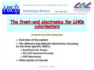
Off-detector & Software development of DAQ System for the EUDET calorimeters Tao Wu On behalf of CALICE-UK Collaboration
EUDET DAQ Targets • Maximizing to use of off-the-shelf commercial components, cheap, scalable and maintainable • Provide well-defined interfaces between DAQ components to allow for minimizing costs and development cycles; • A control system to easily integrate the rest of sub-systems of detectors • Software to build events from bunch train data and disparate sources into single event data • Manage network and data storage EUDET/CALICE UK DAQ
DAQ Mechanical Design targets • Targeting EUDET Module and ILC/CALICE; • Aim to develop a generic system e.g. ECAL/HCAL • Triggerless DAQ system: use C&C instead • All data are sent off detector within a bunch train • Use bunch struct. as advantages: 1ms in bunch train, read out data within 200ms of inter-train gap; • DAQ system will also control power cycling of readout ASICs • A funnel-like DAQ to collect, wrap and transmit data in stages before sending to central storage EUDET/CALICE UK DAQ
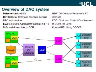
DAQ Architecture Overview e.g. ECAL Slab • Slab hosts VFE chips (ASICs) • Detector Interface connected to Slabs • LDA servicing DIFs • Link/Data Aggregator • LDAs read out by ODR via opto-links • Off-Detector Receiver • PC hosts ODR • PCI-Express driver software • Local Software DAQ • Full blown Software DAQ DIF LDA Opto Ccc- & Data-link PC ODR Opto Driver EUDET/CALICE UK DAQ
Covered by this talk Covered by Valeria Host PC Host PC ODR ODR PCIe PCIe DIF DIF DIF DIF Detector Unit Detector Unit Detector Unit Detector Unit DAQ Architecture Hierarchy 50-150 Mbps HDMI cabling 1-3Gb Fibre LDA Counting Room C&C Detector Storage LDA 10-100m 0.1-1m EUDET/CALICE UK DAQ
Assemble data into a usable form for processing Logical tasks: Receive from LDA Process e.g. event building Store Current input is Ethernet for testing performance Internal FPGA test data generator; External data stream via network ASICs ASICs ASICs … DIF DIF DIF FE LDA Clock / Fast Control CCC-link Data-link DAQ PC ODR Machine clock ODR Store Current Architecture: ODR EUDET/CALICE UK DAQ
Off Detector Receiver (ODR) • Receives modularized data from LDA • Realized as PCI-Express card, hosted in DAQ PC. • 1-4 Opti-links/card (Gigabit), 4 LDAs/card, 1-2 cards/PC • Buffers and transfers to store as fast as possible • Sends controls and configs to LDA for distribution to DIFs • Performance studies & optimisation on-going Expansion (e.g. 3xSFP) Hardware: • Using commercial FPGA dev-board: • PLDA XPressFX100 • Xilinx Virtex 4, 8xPCIe, 2x SFP (3 more with expansion board) SFPs for optic link B.G., A.M @ RHUL EUDET/CALICE UK DAQ
ODR Data Access Rate transfer the data from ODR memory to the user-program memory via 4 links ~700 MByte/sec by 25 DMA buffers All measurements: single requester thread, no disk write, data copied to the host memory. B.G., A.M @ RHUL EUDET/CALICE UK DAQ
LDA Machine C&C Host PC Host PC Run-Control ODR ODR LDA PCIe PCIe Clock & Control (C&C) board • C&C unit provides machine clock and fast signals to 8x ODR/LDA. • A low jitter and fixed latency; • Logic control (FPGA, connected via USB) • Link Data Aggregator provides next stage fanout to Detector Interfaces • Eg C&C unit 8 LDAs 8 DIFs = 64 DUs. • Signalling over same HDMI type cables • Facility to generate optical link clock (~125-250MHz from ~50MHz machine clock) busy Board is already designed, will be build soon M.P., UCL EUDET/CALICE UK DAQ
EUDET DAQ software: State State = Dead suceed failed Transition = PowerUp Transition = PowerDown Checks status & communications State = Ready Transition = StartRun Transition = EndRun Preparing Run number & type Ending/Finishing State = Running Trans. = StartConfiguration Trans. = EndConfiguration Distributes configurations State = Configured Trans. = BunchTrainStart Trans. = BunchTrainEnd Starts the data taking State = InBunchTrain EUDET/CALICE UK DAQ
Transition: StartRun read system status DAQ PC DAQ PC DAQ PC file file file send run number & type • Files to be written for • book keeping: • system status by DAQ PC • run info by RC PC • system status by FC RC FC Conf DB file file send configurations EUDET/CALICE UK DAQ
Data Storage Scenario I Scenario II Scenario III DAQ PC DAQ PC DAQ PC file in memory RAID Array local disk Central store Central store Central store • Which scenario to choose depending on the bandwidth with which the data gets produced: (1) up to 200Mbit/sec, (2) up to ~1600Mbit/sec, (3) from there on • Estimation of the data rate for the EUDET DAQ prototype has to cope with ~400Mbit/s, however it depends on the detector and the choice of VFE. EUDET/CALICE UK DAQ
Software development and code base Computer Infrastructure DAQ Software: DOOCS framework Application layer Communication Middle layer Device layer Software Libs Sun/Linux Cluster EUDET/CALICE UK DAQ
storage Remote GUI Remote GUI dCache Local GUI Local GUI EVB ROOT DISK DCCP Operator GUI Data streams Operator GUI DS ML DS ML DAQ server BM DISK SC SC FC FC RC GUI RC GUI Fast Image Slow RC Linac ADC ADC ADC ADC ADC ADC DB DAQ Software of DOOCS FC/SC: Fast/Slow Collector BM: Buffer Manager EVB: Event Builder DS: DAQ Server EUDET/CALICE UK DAQ
Adapting DOOCS to EUDET DAQ • Modeling hardware card via device server • Existing: VME, Sedac, Profi-Bus; ODR/LDA/DIF/ASICs • Equipment Name Server (ENS): • Facility(F) / Device(D) / Location(L) / Property (P) • e.g. CALICE.ECAL/ODR/ODR1/Status • F: CALICE.ECAL, CALICE.AHCAL, CALICE.DHCAL • D: ODR, LDA, DIF, ASICs; • L: ODR1,ODR2,ODRX; LDA1,LDA2,LDAX; DIF1,DIF2,DIFX; • Property: X X X ? • Build interface talking to hardware (ODR) as a starting point; • Classify the properties and functionalities of each device for our EUDET DAQ system (DIF, LDA, ODR, etc.) EUDET/CALICE UK DAQ
Future plans • Classify the necessary properties and functions of all hardware components; • Continue their building & testing, debugging & improving meanwhile; • Continue to develop interface to hardware (ODR) talking to DOOCS; • Investigate & define the DIFLDAODR links • How to deal with (a)synchronization for C&C? • Putting (all) components together, test… EUDET/CALICE UK DAQ
Summary • Off-detector Receiver has been built for receiving, event building & data storage; its performance has been testing; • Clock & Control instead of triggers, the board will be built soon; • DOOCS framework is reusable & suitable for our DAQ system. • DAQ software is in designing phase… EUDET/CALICE UK DAQ
DAQ architecture DAQ software Off Detector Receiver (ODR) Link Data Aggregator (LDA) Detector Interface (DIF) Detector Unit ASICs P. Göttlicher, DESY EUDET/CALICE UK DAQ
Current ODR Prototype Host System Gigabit NIC Test source External data stream Off-Detector-Receiver Ethernet Interface Optical fibre data stream data stream Source Selector Buffer pointer Manager Address Buffer Memory data stream Test Data Generator data stream Access pointers Event extracts data stream Used FIFO Read pointers DMA Engine Test Data Generator Control data stream PCI Express Buses data stream Card driver code DMA engine ODR local software Local Storage RAID Array EUDET/CALICE UK DAQ
Current ODR Prototype “Requester”: multithreaded application, data copied to the host memory Supervisor Requester Requester DMA FIFO to User buffer FIFO Dup. ODR VHDL code Write pointer Read pointer Data Buff Data Buff Data Buff DMA data to user buffer(s) (host memory) Multiple instances of the “requester”thread. Each accessing different ODR card or different channel. DMA transfer in maximum 4 k (page size) blocks. EUDET/CALICE UK DAQ
Performance (Int.Data Gen) Establishing optimum number of user-defined DMA buffers. No performance improvement above 20 allocate buffers, Comparison of all channels. Number of data buffers: 20 EUDET/CALICE UK DAQ
Performance (continuation) Improvements in performance when accessing more then one channel.The maximum performance achieved for 3-channels access. Adding additionalChannel (4-channel access) does not yield improvement in transfer rate. EUDET/CALICE UK DAQ
N N+1 N+2 Facilities Devices Locations Properties Entries N,1 N+1,1 N+1,2 N+2,1 N+1,1,1 N+1,2,1 N+2,1,1 N+2,1,2 …,1 …,2 …,1 …,1 …,1 …,2 …,3 K K+1 K+2 K+3 K+4 Equipment Name Server (ENS) • Select between devices of the same type in different facilities in on-line addressing of the control system. • Provide the resolution of the names of the devices used in the control system with one entry per device server. • Define user authentication parameters which are used by the control software to restrict the access to the specified control devices EUDET/CALICE UK DAQ
Client programs Query device name actual data request to the equipment server ENS Facility/Device/Location/Property Addresses of equipment server Equipment device ENS • Facility: CALICE.ECAL, CALICE.AHCAL, CALICE.DHCAL • Device: ODR, LDA, DIF, ASIC1, ASIC2, ASIC3 • Location: ODR1, ODR2, ODRX; LDA1, LDA2, LDAX; DIF1, DIF2, DIFX • Property: X X X ? ENS can signal connections by additional properties, e.g. for device DIF: CALICE.ECAL/DIF/DIF1/ODR_CON CALICE.ECAL/DIF/DIF1/LDA_CON CALICE.ECAL/DIF/DIF1/DEBUG_MODE EUDET/CALICE UK DAQ