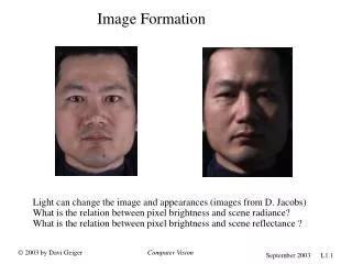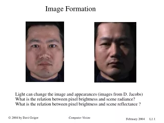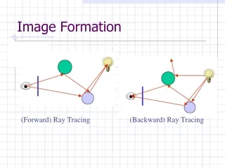

Image Formation
E N D
Presentation Transcript
1. Image Formation Part III
Nuclear Magnetic Resonance
Amanda Golsch BSc, RT(R)(MR)
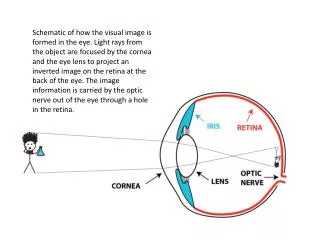
2. What does the N really mean in NMR? The term nuclear in Nuclear Magnetic Resonance refers to the nucleus of an atom. However, this term is slightly intimidating due to many patients envisioning something radioactive. Therefore, the name was changed to Magnetic Resonance Imaging.
3. The Atom The atom has a nucleus that contains protons and neutrons.
Certain nuclei have properties that give them magnetic characteristics. One of the properties is an uneven mass number (protons + neutrons). The uneven mass number makes the substance MR active.
The hydrogen atom is 80% abundant in the human body (water/fat) and contains one proton. These attributes make it MR active.
The proton has mass, a positive charge, and spins on its axis. Moving charged particles make a magnetic field, and the spinning motion of a positively charged particle creates a magnetic field around the proton.
The proton�s magnetic field is termed the magnetic moment.
4. Parallel and Antiparallel Hydrogen protons have a magnetic moment and therefore behave in a certain manner when they are placed in an externally applied magnetic field.
These protons can have two energy states.
Low energy state- These are the protons/spins that align or are in parallel with the magnetic field also known as the B0 field. The circle labeled A demonstrates a spin that is in the low energy parallel state.
High energy state- These are the protons/spins that are aligned anti-parallel, or against the direction of the B0 field. The circle labeled B demonstrates a spin in a high energy antiparallel state.
5. Question 1 T or F: Spins in the low energy state align parallel with the B0 magnetic field. Answer is TrueAnswer is True
6. Parallel and Antiparallel Continued� There will be a slight majority or spin excess in the low energy parallel state. This is known as thermal equilibrium.
During thermal equilibrium, the magnetic moments of spins in the high energy state cancel the effect of those in the low energy state.
Since there is a spin excess or greater number of spins in the low energy state, their magnetic moments add to make a magnetic field known as the net magnetization.
The net magnetization is expressed as a vector. The net magnetization vector is aligned parallel with the B0 field and represents the spin excess and is also know as the proton density.
7. Spins and the X,Y,Z Coordinate System Y= Anterior to Posterior
X= Left to Right
Z= Head to Foot
In the image, the low energy spins are aligned along the Z axis. During excitation the net magnetization vector will be transferred onto the X, Y plane.
8. Precessional Frequency and Calculation Hydrogen protons spin, align, and precess about the axis of the static magnetic field.
Precession has been compared to that of a spinning/wobbling top.
The frequency of precession is important for MR imaging.
Precessional Frequency can be calculated using the Larmor Equation
Gyromagnetic Ratio 1H=42.6 MHz/T. This is the ratio of the spin angular momentum of the proton to it�s magnetic moment.
9. Question 2 At 1.5 T, what is the resonant frequency of a hydrogen proton?
A. 52.5 MHz
B. 63.9 MHz
C. 72.9 MHz
D. 99.8 MHz Answer BAnswer B
10. The RF Pulse RF energy, that is used for MRI is low energy non-ionizing electromagnetic radiation.
The frequency of the RF wave is determined by the Larmor equation.
The radiofrequency is transmitted in short bursts called the RF pulse.
11. What happens when magnetized protons are subjected to an RF pulse? 1. The spins precess in phase, and low energy spins enter the high energy state. This causes the NMV to move into the transverse plane.
The hydrogen spins that precess in phase causes the NMV to precess.
The continuous RF pulse causes some spins in the low energy state to absorb energy from the RF field and move into the high energy state.
As more spins absorb the energy from the RF field, their spin states change, and the NMV tips outward away from the longitudinal Z axis and through the X/Y transverse plane. The X/Y transverse plane is situated 90 degrees from the Z longitudinal plane. This is where the term 90 degree RF pulse comes from.
Increase the amount of RF energy=Increase in flip angle. To double the flip angle you need a four-fold increase in RF power. The amount of power needed to achieve a desired flip angle is dependant on field strength and type of RF coil used for transmitting the FR signal. This is determined during prescan or tuning prior to each scan. Once the flip angle is achieved, the RF is turned off to detect the signal. The NMV precesses through the X/Y plane where it will prescess through a receiver coil.Increase the amount of RF energy=Increase in flip angle. To double the flip angle you need a four-fold increase in RF power. The amount of power needed to achieve a desired flip angle is dependant on field strength and type of RF coil used for transmitting the FR signal. This is determined during prescan or tuning prior to each scan. Once the flip angle is achieved, the RF is turned off to detect the signal. The NMV precesses through the X/Y plane where it will prescess through a receiver coil.
12. How to achieve resonance In order to achieve excitation or resonance, the transmitted RF pulse must match the frequency of precession.
In order to achieve the excitation of water at 1.5T the transmitted RF pulse must be 63.9 MHz. Why?
42.6 MHz/T * 1.5T = 63.9 MHz
42.6 MHz/T is the constant gyromagnetic ratio for hydrogen.42.6 MHz/T is the constant gyromagnetic ratio for hydrogen.
13. Question 3 In order to get signal in MRI a radiofrequency pulse is used to:
A. Relax Spins
B. Align Spins
C. Reduce Spins
D. Excite Spins DD
14. Question 4 After the application of the RF pulse spins:
A. Are reduced
B. Move into the high energy state
C. Relax
D. Attract
CC
15. FID In order to collect signal, there must be transverse magnetization that is in phase. The signal is detected by the receiver coil when the NMV is rotated through the coil.
The signal that is induced in the receiver coil is known as the FID or free induction decay.
The FID decays rapidly after the application of the RF pulse. This is due to a shrinking NMV as it rotates through the X/Y plane. Why does the NMV shrink?
The NMV shrinks because the spins lose phase coherence after the RF pulse is removed.
The peaks show us where the NMV is in phase or perpendicular to the receiver coil. The troughs show us where the NMV is out of phase and perpendicular to the receiver coil. Notice how the FID decays over time.
Note that the signal is plotted in intensity over time. The Fourier Transform transfers the signal from the time domain to the frequency domain (NMR spectrum). It does this through the use of a mathematical process that takes place in the array processor.Note that the signal is plotted in intensity over time. The Fourier Transform transfers the signal from the time domain to the frequency domain (NMR spectrum). It does this through the use of a mathematical process that takes place in the array processor.
16. FID Continued At the same time, yet independently, spins move from the high energy state back into the low energy state. This ultimately leads to the NMV regrowing in the Z axis.
17. Question 5 In order to detect an MRI signal there must be:
A. Transverse magnetization that is zero
B. Longitudinal magnetization that is non zero
C. Longitudinal magnetization that is out of phase
D. Transverse magnetization that is in phase DD
18. Question 6 The signal induced in the receiver coil following the RF pulse is known as:
A. Gradients
B. FID
C. FOV
D. FUN BB
19. Chemical Shift Chemical shift is a difference in precessional frequencies. It is field strength dependent.
Let�s take a look at the chemical shift between fat and water.
Do you know what the chemical shift between fat and water is in ppm?
3.5ppm. This number is constant.
What about at 1.5T?
1.5T * 42.6MHz/T=63.86
63.86=1ppm
Therefore, 63.86 Hz * 3.5= 224Hz
224Hz is the difference in frequency between fat and water at 1.5T
20. Contrast Part IV
Amanda Golsch BSc,RT(R)(MR)
21. Tissue Characteristics The properties of human tissue (fat and water) contribute to the image contrast that we see in MR images.
These properties include proton density, T1 and T2 relaxation times, and flow/motion.
22. Relaxation During the relaxation period that occurs after the RF pulse, there are two simultaneous yet independent processes that occur
T1 Relaxation or Longitudinal Recovery
T2 Relaxation or Transverse Decay
23. Transverse Decay T2 or spin-spin relaxation occurs when the RF pulse is removed. It is due to an exchange of energy between the spins which results in dephasing.
T2 relaxation is the loss or decay of transverse magnetization.
The decay occurs exponentially and can be defined as the time it takes for 63% of a tissues transverse magnetization to decay.
T2 decay can�t be reversed or corrected and different tissues have different T2 times.
Fat = Short T2 decay times
Water = Long T2 decay times
T2 time is measured in milliseconds
24. Question 7 T2 relaxation is the time it takes for
A. 55% of a tissue�s transverse magnetization to decay.
B. 63% of a tissue�s transverse magnetization to decay.
C. 75% of a tissue�s transverse magnetization to decay.
D. 99% of a tissue�s transverse magnetization to decay. BB
25. T2* and T2 Decay Inhomogeneities within the magnetic field and within tissues result in rapid dephasing. In addition, the hydrogen in fat and water precess at different frequencies (chemical shift).
T2* is the combination of T2, field inhomogeneities, and chemical shift. All of these factors result in the rapid loss of transverse magnetization.
The FID decays at a rate based on T2*
T2 is evaluated on spin echo images.
T2* is evaluated on gradient echo images. Note that there are more susceptibility artifacts on T2* images. Why?
There is no 180 degree refocusing pulse that helps to correct field inhomogeneities and chemical shift.
26. T1 Relaxation T1 relaxation occurs at the same time as T2 decay yet it is an independent process.
The longitudinal magnetization regrows along the Z axis as high energy spins return to a low energy state.
It is defined as the time it takes for 63% of a tissue�s longitudinal magnetization to recover.
T1 relaxation is also referred to as spin-lattice relaxation because there is a loss of the spins energy to the surrounding molecular lattice.
Fat=Short T1 times.
Water=Long T1 times
T1 recovery can also be dependent on field strength and temperature.
Increased field strength=Lengthens T1 recovery time.
Increasing a tissues temperature=Lengthens T1 recovery time.
27. Spin Density Spin density represents the number of hydrogen protons in a given volume of tissue.
The proton density is related to the spin excess or the NMV.
CSF has the highest proton (spin) density.
28. Flow and Motion Flowing blood and motion can effect image contrast.
Flow/motion can cause phase ghosting artifacts as well as extraneous signals in images.
This will be discussed in further detail in a later presentation.