Download
1 / 13
220 likes | 749 Views
PS/2 Mouse/Keyboard Port. The Spartan®-3E FPGA Starter Kit board. PS/2 Keyboard Port. The PS2 port was introduced in IBM's Personal System/2 personnel computers .

E N D
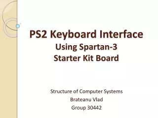
PS/2 Mouse/Keyboard Port The Spartan®-3E FPGA Starter Kit board
PS/2 Keyboard Port • The PS2 port was introduced in IBM's Personal System/2 personnel computers. • PS2 port contains two wires for communication purposes. One wire is for data, which istransmitted in a serial stream. The other wire is for the clock information, which specifieswhen the data is valid and can be retrieved. • The information is transmitted as an 11-bit"packet" that contains a start bit, 8 data bits, an odd parity bit, and a stop bit. • The FPGA prototyping board has a PS2 port and acts as a host.
Timing diagram of a PS2 port. Keyboard Transmission of a Scan Code.
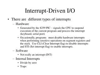
System Transmission of a Command to PS/2 Device. • In addition to data and clock lines, the PS2 port includes connections for power (Vdd)and ground. The power is supplied by the host. In the original PS2 port, Vcc is 5 V. Most current keyboardsand mice can work well with 3.3 V.
Device-to-host communication protocol • A PS2 device and its host communicate via packets. • The data is transmitted in a serial stream. • Transmission begins with a start bit, followed by 8 data bits and an odd parity bit, and endswith a stop bit. • The clock information is carried in a separate clock signal. • The falling edge of the clksignal indicates that the corresponding bit in the data line is valid and can be retrieved. • The clock period of the clksignal is between 60 and100 micro seconds (i.e., 10 kHz to 16.7 kHz), and the datasignal is stable at least 5 micro secondsbefore and afterthe falling edge of the clksignal.
PS2 KEYBOARD SCAN CODE • A keyboard consists of a matrix of keys and an embedded microcontroller that monitors(i.e., scans) the activities of the keys and sends scan codeaccordingly. Three types of keyactivities are observed: • When a key is pressed, the make codeof the key is transmitted. • When a key is held down continuously, a condition known as typematic, the makecode is transmitted repeatedly at a specific rate. By default, a PS2 keyboard transmitsthe make code about every 100 msafter a key has been held down for 0.5 second. • When a key is released, the break codeof the key is transmitted. • The make code is normally1 byte wide and represented by two hexadecimal numbers. For example, the make codeof the Akey is 1C. This code can be conveyed by one packet when transmitted. The makecodes of a handful of special-purpose keys, which are known as the extended keys, can have2 to 4 bytes. For example, the make code ofthe upper arrow on the right is EO 75. Multiple packets are needed for the transmission. • The break codes of the regular keys consist of FO followed by the make code of the key.For example, the break code of the Akey is FO 1C. • The PS2 keyboard transmits a sequence of codes according to the key activities. Forexample, when we press and release the A key, the keyboard first transmits its make codeand then the break code:1C FO 1C
Scan code of the PS2 keyboard • If we hold the key down for awhile before releasing it, the make code will be transmittedmultiple times:1C 1C 1C 1C …… 1C FO 1C. • Multiple keys can be pressed at the same time. For example, we can first press the shiftkey (whose make code is 12) and then the A key, and release the A key and then release theshift key. The transmitted code sequence follows the make and break codes of the twokeys:12 1C FO 1C FO 12.
Scan Codes for PS/2 Keyboard • If the defaultscan code is used, no commands will need to be sent to the keyboard.
The PS/2 Serial Data Transmission Protocol • The scan codes are sent serially using 11 bits on the bi-directional data line.When neither the keyboard nor the computer needs to send data, the data lineand the clock line are High (inactive). • The transmission of a single key or command consists ofthe following components: • A start bit ('0') • 8 data bits containing the key scan code in low to high bit order • Odd parity bit such that the eight data bits plus the parity bit are an oddnumber of ones • A stop bit ('1')
The PS/2 Serial Data Transmission Protocol • When implementing the interface code, it will benecessary to filter the slow keyboard clock to ensure reliable operation with thefast logic inside the FPGA chip. Whenever an electrical pulse is transmitted ona wire, electromagnetic properties of the wire cause the pulse to be distortedand some portions of the pulse may be reflected from the end of the wire. • One approach that solves the reflected pulse problem is tofeed the PS/2clock signal into an 8-bit shift register • This prevents noise and ringing on the clock line from causingoccasional extra clocks during the serial-to-parallel conversion in the FPGAchip. • A few keyboards and mice will work without the clock filter and many will not. • They all will work with the clock filter, and it is relatively easy to implement.
The PS/2 Serial Data Transmission Protocol • Upon completion of each command byte, the keyboard will send anacknowledge (ACK) signal, FA, if it received the data successfully. If thesystem does not release the data line, the keyboard will continue to generate theclock, and upon completion, it will send a ‘re-send command’ signal, FE or FC,to the system. A parity error or missing stop bit will also generate a re-sendcommand signal.
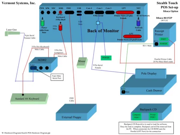
The Spartan®-3E FPGA Starter Kit board • Includes a PS/2 mouse/keyboard port and thestandard 6-pin mini-DIN connector, labeled J14 on the board. Only pins 1 and 5 of theconnector attach to the FPGA.
The Spartan®-3E FPGA Starter Kit board PS/2 Bus Timing Waveforms