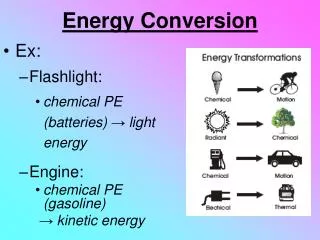
Wind Energy Conversion Systems April 21-22, 2003
320 likes | 594 Views
Wind Energy Conversion Systems April 21-22, 2003. K Sudhakar Centre for Aerospace Systems Design & Engineering Department of Aerospace Engineering http://www.casde.iitb.ac.in/~sudhakar. Horizontal Axis WECS. Energy extraction at a plane normal to wind stream. Rotor plane - a disc.

Wind Energy Conversion Systems April 21-22, 2003
E N D
Presentation Transcript
Wind Energy Conversion SystemsApril 21-22, 2003 K Sudhakar Centre for Aerospace Systems Design & Engineering Department of Aerospace Engineering http://www.casde.iitb.ac.in/~sudhakar
Horizontal Axis WECS Energy extraction at a plane normal to wind stream. Rotor plane - a disc
Aerodynamics of Wind Turbines Aerodynamics Forces and Moments on a body in relative motion with respect to air Topics of intense study aerospace vehicles, road vehicles, civil structures, wind turbines, etc.
Atmosphere • International Standard Atmosphere • Sea level pressure = 101325 Pa • Sea level temperature = 288.16 K (IRA 303.16) • Sea level density = 1.226 kg/m^3 (IRA 1.164) • dt/dh = -0.0065 K/m • p/pSL = (t/tSL)5.2579 • Planetary boundary layer extends to 2000m V(50 m) / V(20 m) = 1.3 city = 1.2 grassy = 1.1 smooth
A1, V1 A2, V2 Bernoulli Equation p + 0.5 V2 = constant Incompressible flows; along a streamline, . . Internal flows: Conservation of mass; A V = constant If is constant, A1 V1 =A2 V2
A V p pd+ pd- A d Vd A 1 V1 p Actuator Disc Theory A V= A d Vd =A1 V1 ; mass flow rate, m = Ad Vd P = 0.5 m (V2 - V12) = 0.5 Ad Vd (V2 - V12) T = m (V- V1) = Ad Vd (V- V1) = Ad ( pd- - pd+) pd- - pd+ = Vd (V- V1)
A V p pd+ pd- A d Vd A 1 V1 p Actuator Disc Theory p + 0.5 V2 = pd- + 0.5 Vd2 p + 0.5 V12 = pd+ + 0.5 Vd2 pd- - pd+ = 0.5 (V2- V12 ) = Vd (V- V1) Vd = 0.5 (V+ V1) ; Vd = V( 1 - a); V1 = V( 1 - 2 a) P = 0.5 Ad Vd (V2 - V12) = 0.5 Ad Vd 2Vd (V- V1) = Ad Vd2(V- V1) = Ad V2(1 - a)2 2aV = 2 Ad V3 a (1 - a)2
Actuator Disc Theory P = 2 Ad V3 a (1 - a)2 Non-dimensional quantities, CP= P / (0.5 Ad V3 ) ; CQ = Q/ (0.5 AdR V2 ) CT = T/ (0.5 Ad V2 ) ; = r / V CP = 4 a (1 - a)2 ;CT = 4 a (1 - a) dCP/da = 0 a = 1/3 CP-max = 16/27 ; CT @CP-max = 8/9 a = 1/3 CT-max = 1 ; CP @CT-max = 1/2 a = 1/2
Rotor & Blades Energy extraction through cranking of a rotor Cranking torque supplied by air steam Forces / moments applied by air stream? Blade element theory of rotors?
M F *P1 V Po Aerodynamics Aerodynamics - Forces and Moments on a body in relative motion with respect to air
y n u rMRP ds V Forces & Moments Basic Mechanisms • Force due to normal pressure, p = - p ds n • Force due to tangential stress, = ds ( n = 0)
drag V Drag & Lift • D - Drag is along V • L - Lift is the force in the harnessed direction How to maximise L/D
Skin friction drag, Df Pressure drag, DP Drag For steam lined shapes Df >> DP For bluff bodies DP >> Df
Streamlining! Equal Drag Bodies Airfoil of chord 150 mm 1 mm dia wire
r ,Q Tower loads V Wind Turbine Typical Vertical Axis WECS - Rotor with n-blades Cranked by airflow. Cranking torque?
Lift drag V Wind Turbine Rotor How to compute Q = Torque, T = Tower load
Why non-dimensional Coefficients • With dimensional values • At each (, , , V , a, c) measure L, D, M • Many tests required • With non-dimensional coefficients • At desired Re, M, and V • for each measure L, D, M • Convert to CL, CD, CM • At any other and V compute L, D M
Camber line t h V C Airfoil Characteristics h(x) 0 camber symmetric airfoil (h/c)max and (x/c) @ (h/C)max (t/c)max and (x/c) @ (t/c)max Leading edge radius
stall Moment Ref Pt = 0.25 c CL CM CD i 13o Airfoil Characteristics i = f(h/c)max CM = constant = f(h/c)max CL = dCL/d = 2 rad-1 = 0.11 deg -1 CLo = f (h/c)max Special airfoils for wind turbines with high t/c @ low Re SERI / NREL
, Q Cranking Torque? • Air cranks rotor equal, opposite reaction on air • Rotor angular velocity, • Torque on rotor Q • Angular velocity of air downstream of rotor, = 2a’ • Angular velocity at rotor mid-plane, 0.5 = a’ • a’- circumferential inflow
dr r , Q Cranking Torque? = 2a’
CL CD Flow velocities r a’ r V W a V = - CL, CD = f () Cx = CLSin - CD Cos = CLSin ( 1 - Cot ) CT = CLCos +CD Sin = CLCos ( 1+ Tan )
Betz 16/27 CP Cpi - Energy extraction is through cranking