Download
1 / 65
650 likes | 821 Views
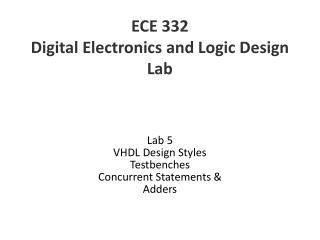
ECE 332 Digital Electronics and Logic Design Lab. Lab 5 VHDL Design Styles Testbenches Concurrent Statements & Adders. VHDL Design Styles. VHDL Design Styles. BEHAVIORAL. DATAFLOW. STRUCTURAL. SYTHESIZABLE. NON- SYNTHESIZABLE. “concurrent” statements. components and

E N D
ECE 332Digital Electronics and Logic Design Lab Lab 5 VHDL Design Styles Testbenches Concurrent Statements & Adders
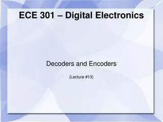
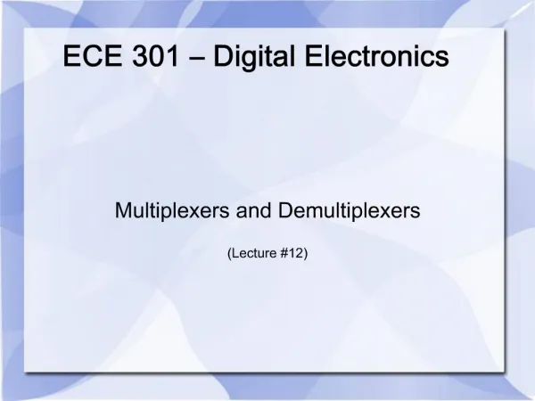
VHDL Design Styles VHDL Design Styles BEHAVIORAL DATAFLOW STRUCTURAL SYTHESIZABLE NON-SYNTHESIZABLE “concurrent” statements components and interconnects “sequential” statements • State machines • Registers • Test Benches • Modeling IP VHDL subset most suitable for synthesis ECE 332 George Mason University
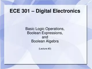
XOR3 Example ECE 332 George Mason University
Entity XOR3 (same for all architectures) LIBRARY ieee; USE ieee.std_logic_1164.all; ENTITYxor3IS PORT( A : IN STD_LOGIC; B : IN STD_LOGIC; C : IN STD_LOGIC; Result : OUT STD_LOGIC ); END xor3; ECE 332 George Mason University
Dataflow Architecture ARCHITECTUREdataflowOFxor3IS SIGNAL U1_out: STD_LOGIC; BEGIN U1_out <= A XORB; Result <= U1_outXOR C; ENDdataflow; U1_out ECE 332 George Mason University
Dataflow Description • Describes how data moves through the system and the various processing steps. • Dataflow uses series of concurrent statements to realize logic. • Dataflow is most useful style when series of Boolean equations can represent a logic used to implement simple combinational logic • Concurrent statements are evaluated at the same time; thus, the order of these statements doesn’t matter • This is not true for sequential/behavioral statements • This order… • U1_out <= A XORB; • Result <= U1_outXOR C; • Is the same as this order… • Result <= U1_outXOR C; • U1_out <= A XORB; ECE 332 George Mason University
Structural Architecture (XOR3 gate) ARCHITECTUREstructuralOF xor3IS SIGNALU1_OUT:STD_LOGIC; COMPONENT xor2IS PORT( I1 : IN STD_LOGIC; I2 : IN STD_LOGIC; Y : OUT STD_LOGIC ); END COMPONENT; BEGIN U1: xor2PORT MAP ( I1 => A, I2 => B, Y => U1_OUT); U2: xor2PORT MAP ( I1 => U1_OUT, I2 => C, Y => Result); ENDstructural; A B XOR3 Result C ECE 332 George Mason University
Component and Instantiation • Named association connectivity (recommended) COMPONENTxor2IS PORT( I1 : IN STD_LOGIC; I2 : IN STD_LOGIC; Y : OUT STD_LOGIC ); END COMPONENT; BEGIN U1: xor2PORT MAP ( I1 => A, I2 => B, Y => U1_OUT); ... LOCAL WIRE COMPONENT PORT NAME ECE 332 George Mason University
Component and Instantiation • Positional association connectivity (not recommended) COMPONENTxor2IS PORT( I1 : IN STD_LOGIC; I2 : IN STD_LOGIC; Y : OUT STD_LOGIC ); END COMPONENT; BEGIN U1: xor2PORT MAP (A, B, U1_OUT); ... ECE 332 George Mason University
Structural Description • Structural design is the simplest to understand. This style is the closest to schematic capture and utilizes simple building blocks to compose logic functions. • Components are interconnected in a hierarchical manner. • Structural descriptions may connect simple gates or complex, abstract components. • Structural style is useful when expressing a design that is naturally composed of sub-blocks. ECE 332 George Mason University
Behavioral Architecture (XOR3 gate) ARCHITECTUREbehavioralOF xor3IS BEGIN PROCESS (A,B,C) BEGIN IF ((A XOR B XOR C) = '1') THEN Result <= '1'; ELSE Result <= '0'; END IF; END PROCESS; END behavioral; ECE 332 George Mason University
Behavioral Description • It accurately models what happens on the inputs and outputs of the black box (no matter what is inside and how it works). • This style uses PROCESSstatementsinVHDL. • Statements are executed in sequence in a process statement order of code matters! ECE 332 George Mason University
Single Wire Versus Bus SIGNAL a : STD_LOGIC; a 1 wire SIGNAL b : STD_LOGIC_VECTOR(7 downto 0); b bus 8 ECE 332 George Mason University
Standard Logic Vectors SIGNAL a: STD_LOGIC; SIGNALb: STD_LOGIC_VECTOR(3 DOWNTO 0); SIGNALc: STD_LOGIC_VECTOR(3 DOWNTO 0); SIGNALd: STD_LOGIC_VECTOR(7 DOWNTO 0); SIGNALe: STD_LOGIC_VECTOR(15 DOWNTO 0); SIGNALf: STD_LOGIC_VECTOR(8 DOWNTO 0); ………. a <= '1'; b <= "0000"; -- Binary base assumed by default c <= B"0000"; -- Binary base explicitly specified d <= "0110_0111"; -- You can use '_' to increase readability e <= X"AF67"; -- Hexadecimal base f <= O"723"; -- Octal base ECE 332 George Mason University
Single versus Double Quote • Use single quote to hold a single bit signal • a <= '0', a <='Z' • Use double quote to hold a multi-bit signal • b <= "00", b <= "11" ECE 332 George Mason University
Testbenches ECE 332 George Mason University
Testbench Block Diagram Testbench Processes Generating Stimuli Design Under Test (DUT) Observed Outputs ECE 332 George Mason University
Testbench Defined • A testbench applies stimuli (drives the inputs) to the Design Under Test (DUT) and (optionally) verifies expected outputs. • The results can be viewed in a waveform window or written to a file. • Since a testbench is written in VHDL, it is not restricted to a single simulation tool (portability). • The same testbench can be easily adapted to test different implementations (i.e. different architectures) of the same design. ECE 332 George Mason University
Testbench Anatomy ENTITYtbIS --TB entity has no ports ENDtb; ARCHITECTUREarch_tbOFtbIS --Local signals and constants COMPONENT TestComp -- All Design Under Test component declarations PORT ( ); END COMPONENT; ----------------------------------------------------- BEGIN DUT:TestComp PORT MAP( -- Instantiations of DUTs ); testSequence: PROCESS -- Input stimuli END PROCESS; ENDarch_tb; ECE 332 George Mason University
Testbench for XOR3 LIBRARYieee; USEieee.std_logic_1164.all; ENTITY xor3_tbIS ENDxor3_tb; ARCHITECTURExor3_tb_architectureOFxor3_tbIS -- Component declaration of the tested unit COMPONENTxor3 PORT( A : IN STD_LOGIC; B : IN STD_LOGIC; C : IN STD_LOGIC; Result : OUT STD_LOGIC ); END COMPONENT; -- Stimulus signals - signals mapped to the ports of tested entity SIGNAL A, B, C :STD_LOGIC; SIGNAL test_result : STD_LOGIC; BEGIN DUT : xor3 PORT MAP ( A => A, B => B, C => C, Result => test_result); ECE 332 George Mason University
Testbench for XOR3 (2) PROCESS BEGIN A <= ‘0’; B <= ‘0’; C <= ‘0’; WAIT FOR 10 ns; A <= ‘0’; B <= ‘0’; C <= ‘1’; WAIT FOR 10 ns; A <= ‘0’; B <= ‘1’; C <= ‘0’; WAIT FOR 10 ns; A <= ‘0’; B <= ‘1’; C <= ‘1’; WAIT FOR 10 ns; A <= ‘1’; B <= ‘0’; C <= ‘0’; WAIT FOR 10 ns; A <= ‘1’; B <= ‘0’; C <= ‘1’; WAIT FOR 10 ns; A <= ‘1’; B <= ‘1’; C <= ‘0’; WAIT FOR 10 ns; A <= ‘1’; B <= ‘1’; C <= ‘1’; WAIT; END PROCESS; ENDxor3_tb_architecture; ECE 332 George Mason University
Testbench waveform ECE 332 George Mason University
Dataflow VHDL Major instructions Concurrent statements • concurrent signal assignment () • conditional concurrent signal assignment • (when-else) • selected concurrent signal assignment • (with-select-when) • generate scheme for equations • (for-generate)
Value N … Value N-1 Target Signal Value 2 Value 1 Condition N-1 Condition 2 Condition 1 Conditional concurrent signal assignment When - Else target_signal <= value1whencondition1else value2whencondition2else . . . valueN-1whenconditionN-1else valueN; 0 1 .… 0 1 0 1
Operators • Relational operators • Logic and relational operators precedence = /= < <= > >= Highest not = /= < <= > >= and or nand nor xor xnor Lowest
Priority of Logic and Relational Operators compare a = bc Incorrect … when a = b and c else … equivalent to … when (a = b) and c else … Correct … when a = (b and c) else …
Tri-state Buffer – example ena output input LIBRARY ieee; USE ieee.std_logic_1164.all; ENTITY tri_state IS PORT ( ena: IN STD_LOGIC; input: IN STD_LOGIC_VECTOR(7 downto 0); output: OUT STD_LOGIC_VECTOR (7 DOWNTO 0) ); END tri_state; ARCHITECTURE tri_state_dataflow OF tri_state IS BEGIN output <= input WHEN (ena = '0') ELSE (OTHERS => 'Z'); END tri_state_dataflow; OTHERS means all bits not directly specified,in this case all the bits.
Dataflow VHDL Major instructions Concurrent statements • concurrent signal assignment () • conditional concurrent signal assignment • (when-else) • selected concurrent signal assignment • (with-select-when) • generate scheme for equations • (for-generate)
Selected concurrent signal assignment With –Select-When withchoice_expressionselect target_signal <= expression1whenchoices_1, expression2whenchoices_2, . . . expressionNwhenchoices_N; choices_1 expression1 expression2 choices_2 target_signal expressionN choices_N choice expression
Allowed formats of choices_k WHEN value WHEN value_1 to value_2 WHEN value_1 | value_2 | .... | value N this means boolean “or”
Allowed formats of choice_k - example WITH sel SELECT y <= a WHEN "000", b WHEN "011" to "110", c WHEN "001" | "111", d WHEN OTHERS;
MLU: Entity Declaration LIBRARY ieee; USE ieee.std_logic_1164.all; ENTITY mlu IS PORT( NEG_A : IN STD_LOGIC; NEG_B : IN STD_LOGIC; NEG_Y : IN STD_LOGIC; A : IN STD_LOGIC; B : IN STD_LOGIC; L1 : IN STD_LOGIC; L0 : IN STD_LOGIC; Y : OUT STD_LOGIC ); END mlu;
MLU: Architecture Declarative Section ARCHITECTURE mlu_dataflow OF mlu IS SIGNAL A1 : STD_LOGIC; SIGNAL B1 : STD_LOGIC; SIGNAL Y1 : STD_LOGIC; SIGNAL MUX_0 : STD_LOGIC; SIGNAL MUX_1 : STD_LOGIC; SIGNAL MUX_2 : STD_LOGIC; SIGNAL MUX_3 : STD_LOGIC; SIGNAL L:STD_LOGIC_VECTOR(1 DOWNTO 0);
MLU - Architecture Body BEGIN A1<=NOT A WHEN (NEG_A='1') ELSE A; B1<=NOT B WHEN (NEG_B='1') ELSE B; Y<=NOT Y1 WHEN (NEG_Y='1') ELSE Y1; MUX_0<=A1 AND B1; MUX_1<=A1 OR B1; MUX_2<=A1 XOR B1; MUX_3<=A1 XNOR B1; L <= L1 & L0; with (L) select Y1<=MUX_0 WHEN "00", MUX_1 WHEN "01", MUX_2 WHEN "10", MUX_3 WHEN OTHERS; END mlu_dataflow;
Data-flow VHDL Major instructions Concurrent statements • concurrent signal assignment () • conditional concurrent signal assignment • (when-else) • selected concurrent signal assignment • (with-select-when) • generate scheme for equations • (for-generate)
For Generate Statement For - Generate label:FORidentifier IN rangeGENERATE BEGIN {Concurrent Statements} END GENERATE [label];
PARITY: Entity Declaration LIBRARYieee; USEieee.std_logic_1164.all; ENTITYparityIS PORT( parity_in : IN STD_LOGIC_VECTOR(7 DOWNTO 0); parity_out : OUT STD_LOGIC ); ENDparity;
xor_out(1) PARITY: Block Diagram xor_out(2) xor_out(3) xor_out(4) xor_out(5) xor_out(6)
PARITY: Architecture ARCHITECTUREparity_dataflowOFparityIS SIGNALxor_out: std_logic_vector (6 downto 1); BEGIN xor_out(1) <= parity_in(0) XORparity_in(1); xor_out(2) <= xor_out(1) XORparity_in(2); xor_out(3) <= xor_out(2) XORparity_in(3); xor_out(4) <= xor_out(3) XORparity_in(4); xor_out(5) <= xor_out(4) XORparity_in(5); xor_out(6) <= xor_out(5) XORparity_in(6); parity_out <= xor_out(6) XORparity_in(7); ENDparity_dataflow;
xor_out(1) xor_out(0) PARITY: Block Diagram (2) xor_out(2) xor_out(3) xor_out(4) xor_out(5) xor_out(6) xor_out(7)
PARITY: Architecture ARCHITECTUREparity_dataflowOFparityIS SIGNALxor_out: STD_LOGIC_VECTOR (7 downto 0); BEGIN xor_out(0) <= parity_in(0); xor_out(1) <= xor_out(0) XORparity_in(1); xor_out(2) <= xor_out(1) XORparity_in(2); xor_out(3) <= xor_out(2) XORparity_in(3); xor_out(4) <= xor_out(3) XORparity_in(4); xor_out(5) <= xor_out(4) XORparity_in(5); xor_out(6) <= xor_out(5) XORparity_in(6); xor_out(7) <= xor_out(6) XORparity_in(7); parity_out <= xor_out(7); ENDparity_dataflow;
PARITY: Architecture (2) ARCHITECTUREparity_dataflowOFparityIS SIGNALxor_out: STD_LOGIC_VECTOR (7 DOWNTO 0); BEGIN xor_out(0) <= parity_in(0); G2: FOR i IN1TO7GENERATE xor_out(i) <= xor_out(i-1) XORparity_in(i); END GENERATE; parity_out <= xor_out(7); ENDparity_dataflow;
Simple Rules For combinational logic, use only concurrent statements • concurrent signal assignment () • conditional concurrent signal assignment • (when-else) • selected concurrent signal assignment • (with-select-when) • generate scheme for equations • (for-generate)
Simple Rules • For circuits composed of: • simple logic operations (logic gates) • simple arithmetic operations (addition, subtraction, multiplication) • shifts/rotations by a constant • Use • concurrent signal assignment ()
Simple Rules • For circuits composed of • multiplexers • decoders, encoders • tri-state buffers • Use: • conditional concurrent signal assignment (when-else ) • selected concurrent signal assignment (with-select-when)
Left versus Right Side Left side <= <= when-else with-select <= Right side • Expressions including: • Internal signals (defined • in a given architecture) • Ports of the mode • - in • - inout • - buffer • Internal signals (defined • in a given architecture) • Ports of the mode • - out • - inout • - buffer (don’t recommend • using buffer in this class)