Shunt-LDO testing
Shunt-LDO testing. Laura Gonella , M. Barbero , H. Krueger 21/02/2010. Shunt-LDO reminder. Combination of a LDO and a shunt transistor. Shunt-LDO: simplified schematic. 2 Shunt-LDOs in parallel: equivalent circuit. Shunt-LDO can be placed in parallel without problems due to mismatch

Shunt-LDO testing
E N D
Presentation Transcript
Shunt-LDO testing Laura Gonella, M. Barbero, H. Krueger 21/02/2010
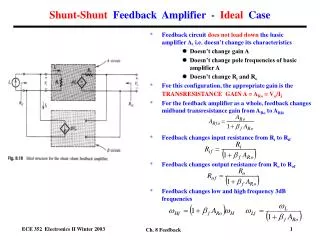
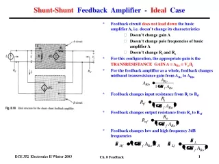
Shunt-LDO reminder Combination of a LDO and a shunt transistor Shunt-LDO: simplified schematic 2 Shunt-LDOs in parallel: equivalent circuit • Shunt-LDO can be placed in parallel without problems due to mismatch • Shunt-LDO with different Voutcan be placed in parallel • Shunt-LDO can cope with increased Iin • Normal LDO operation when shunt circuitry is off • Shunt regulation circuitry const Iload • LDO regulation loop constant Vout LDO compensates Vout difference LG - FE-I4 testing meeting - 21/02/2011
Shunt-LDO in FEI4 • 2 shunt-LDO regulators in FEI4 • Reg1 input connected to DC-DC output • Reg2 independent • Biasing currents generated internally • Vref has to be provided externally • Rint, Rext, and VDDShunt connection selected externally to configure the device as Shunt-LDO or LDO Reg2 Reg1 LG - FE-I4 testing meeting - 21/02/2011 LDO Shunt-LDO with Rint Shunt-LDO with Rext
Test board • Modified FE-I4 SCC allows testing of • Both regulators, independently or in parallel • FE-I4 with direct powering or Shunt-LDO/LDO powering • Reduced FE-I4 testing capability (wafer level testing) Current input Vbp measurement Rint, Rext, VDDShunt Iin2 measurement Iin1 measurement 1 VDDD 1 VDDA 1 GND Vref1 Vref2 External load LG - FE-I4 testing meeting - 21/02/2011
Test setup • For Shunt-LDO characterization • Labviewsoftwaredevelopedby D. ArutinovforShunt-LDOprototypetesting • Iin and IloadprovidedbyprogrammableKeithleysourcemeter • Vin, Vout, Vref/Vbp measured automatically using Keithley multimeters • For FE-I4 characterization • USBPix LG - FE-I4 testing meeting - 21/02/2011
Test plan • Tests both regulators in FE-I4 as Shunt-LDO and pure LDO • Test the 2 Shunt-LDO regulators in parallel • Test FE-I4 with Shunt-LDO/LDO powering • Test assemblies with Shunt-LDO/LDO powering • New card needed LG - FE-I4 testing meeting - 21/02/2011
Reg2: Shunt-LDO I show results with Rint. Those with Rext are the same. • Output voltage is generated as soon as all transistors saturate • A few unexpected features, which however do not harm the regulator operation • Second jump at higherIin • Vout < 2Vref, and decreases with increasing Iin Voltagegeneration LG - FE-I4 testing meeting - 21/02/2011
Vingeneration: second jump • Depends on Vout • 1.2V: @0.220A , 1.3V: @0.270A, 1.4: @0.330A, 1.5: @0.390A • Investigation of biases: VDDShunt • Connected to Vin • Bias for A3 and for the biasing circuitry • Tried to set it to a constant value or connect to Vout → no effect on second jump • Temperatureeffect? • Tried to cool board during test → no effect on second jump • More investigation needed • Could it be a board feature? LG - FE-I4 testing meeting - 21/02/2011
Vin generation: Vout value and behavior • Hypothesis: Vdrop on the ground line which effectively decreases the Vref • Vref is referred to the board gnd, whilst Vout is measured wrt the chip gnd • Measurement of gnd difference between chip gnd and board gnd • Results show that this hypothesis is valid after the second jump LG - FE-I4 testing meeting - 21/02/2011
Reg2: Shunt-LDO • Output voltage is stable for increasing Iload • Input and output voltage collapse when Iload = Iin Loadregulation Iin = 0.480A LG - FE-I4 testing meeting - 21/02/2011
Reg2: LDO • Also for the LDO the voltage generation works fine • Again, Vout ≠ 2Vref Voltagegeneration LG - FE-I4 testing meeting - 21/02/2011
Reg1 • Need to configure the DC-DC regulator properly • Connect DC-DC input to Vin • Power the LVDS receivers in FE-I4 to set the AUX-CLK (i.e. the internal switches) to a defined set to avoid connection between DC-DC output and GND • Once the DC-DC is properly configured the Reg1 behaves as Reg2 • At first the DC-DC regulator was left floating and the results did not look good... • Vin and Vout collapse at certain value of Iin/Iload → The current is not flowing in the Shunt-LDO but somewhere else... LG - FE-I4 testing meeting - 21/02/2011
Reg1 results Shunt-LDO Voltage generation Load regulation LDO Voltage regulation LG - FE-I4 testing meeting - 21/02/2011
Conclusion • Both regulators have been operated • Operation of Reg1 requires proper configuration of the DC-DC • Voltage generation and load current regulation are fine • Still to understand second jump in voltage generation characteristic and Vout value and behavior -> no show stopper • Some investigations have been done already, need to think about it a bit more • Also, compare with results on LDO. In this case only the voltage regulation loop is used • First results are encouraging. Characterization goes on... LG - FE-I4 testing meeting - 21/02/2011