Download
1 / 60
600 likes | 702 Views
This IEEE meeting focuses on developing a standard for the interface between rail and highway subsystems at a highway rail intersection. The goal is to enhance safety and interoperability through well-defined interface attributes. Topics include review of wayside equipment interface and identification of messages. The agenda covers key objectives and the standards process, ensuring compliance with consensus standards and government policies. The National ITS Architecture plays a crucial role in supporting standards development, with terminators and interfaces detailed for rail operations and traffic management. Key standards already published and upcoming projects are discussed, along with funding and support from sponsoring committees such as FRA. This standard aims to create a practical and valuable framework for the industry, with a timeline for drafting, review, ballot, and publication.

E N D
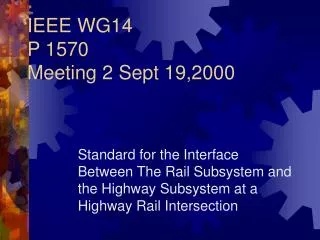
IEEE WG14P 1570Meeting 2 Sept 19,2000 Standard for the Interface Between The Rail Subsystem and the Highway Subsystem at a Highway Rail Intersection
AGENDA • 9:00 Introductions • 9:30 Review of Last Meeting / Draft Standard • 10:00 Review of Wayside Equipment I/F Std • Noon Lunch • 1:00 Rail to Highway Messages • 2:00 Highway to Rail Messages • 3:30 Closing Business
WG 14 Objectives • Develop a Practical Standard of Value to the Industry • Develop Standard in a Professional Environment • All Comments solicited and evaluated • Schedule (based on 6/00 Kickoff) • 8/01 First Draft • 2/02 Complete Initial Review • 8/02 Ballot and final Review • 2/03 Publish • Provide support for operations center I/F
P1570 Scope This standard defines the logical and physical interfaces, and the performance attributes for the interface between the rail subsystem and the highway subsystem at a highway rail intersection.
P1570 Purpose Coordination between the rail subsystem and the highway subsystem is part of creating a National Intelligent Transportation System covering multiple modes of transportation. Existing standards address analog interfaces between these subsystems at the highway rail intersection. This standard will extend that information to include serial digital communication. Standardizing the interface will allow interoperability between a wide variety of equipment and enhance safety through a set of well-defined interface and performance attributes.
Today’s Objectives • Brief Review of Last Meeting • Review of Wayside Equipment Interface Specification • Identify Messages and Attributes of Interface Messages
Review of Last Meeting • Objectives, Scope and Purpose • IEEE Standards Process • ITS Architecture/ HRI Stds Rqmts Pkg 12 • NTCIP Communications Infrastructure • AREMA, FRA and MUTCD Rqmts • Process / Strawman
IEEE Standards Process • Highlighted that US Government policy requires use of consensus standards in regulatory efforts. • Characteristics of Consensus Standards • Due Process • Openness • Consensus • Balance • Right of Appeal
IEEE STANDARDS PROCESS • What IEEE Provides • Automatic ANSI Certification • Complies with PL 104-113 & OMB A-119 • Rules, Procedures & Oversight already in place at no cost to industry • Professional standards experts available to assist at no cost • Large reservoir of existing case law • IEEE assumes standards liability risk
IEEE Standards Process • Sponsoring Committee is the Rail Transit Interface Standards Committee • Selected as sponsoring committee at FRA meeting with AAR, AREMA, ITE, APTA, IEEE • FRA likely to provide funding for standards preparation support and communications consultant support
IEEE Standards Process • Key Standards Published to Date • IEEE 1473-1999 Communications Protocol • IEEE 1474.1-1999 Communications Based Train Control Performance & Function • IEEE 1482.1-1999 Event Recorder • IEEE 1475-1999 Propulsion, Braking & Train Control • IEEE 1477-1998 Passenger Information • IEEE 1483-2000 Software Verification For Vital Functions • IEEE 1476-2000 Auxiliary Power Interface • IEEE 11-1999 Electric Motors
IEEE Standards Process • Standards in Process • Environmental - Being balloted • Rail TCIP - Underway • Battery Physical Interface - Underway • Software Documentation - Underway • Electronic Control - Underway • NiCad Battery Peformance - PAR stage • HRI - Underway • Central Control CBTC Graphic Interface - Underway • Vehicle/Wayside Communication Protocol - Proposal
Current Architecture Version • Published December 1999 User Services Phase I Competition 1993 1994 Phase II Architecture Published 1995 HRI Update Version 3.0 Version 2.0 1996 1997 1998 1999
The National ITS Architecture: HRI Update Summary • Rail Operations and Wayside Equipment Added as Terminators • Terminators are used on edge of Architecture • Developed Standards Requirement Package 12 as starting point for development of HRI Interface Standard
Rail Operations Traffic Management The National ITS Architecture: HRI User Service Addition (2) T R A I N A P P R O A C H I N G Variable Message Signs Vehicle Presence Detection Vehicle Barriers Traffic Signals Track Circuits Roadway Subsystem Automatic Gates/Barriers Vehicle Subsystem Surveillance Wayside Equipment Terminator Wayside Equipment Intelligent Controller Short Range Communications Rail Operations Terminator • Traffic Management Subsystem
How Can Architecture Support Standards Development • Definition of Interfaces in National ITS Architecture serves as starting point for standards effort (Define interfaces in greater detail) • Where to find definition of HRI Interfaces: • Standards Requirements Package 12: Highway Rail Intersections • Available on CD-ROM- Archdocs/Standards Requirements Document (pages 640-663) • Essential information also on CD-ROM hypertext under Hypertext View/Standards Requirements
Stds Rqmt Package 12: Outline 1 Introduction to Standards Requirements Documentation 2 Introduction: Highway Rail Intersections (HRI) 3 Transaction Sets for Highway Rail Intersection Interfaces 3.1 Rail Operations and Traffic Management Subsystem 3.2 Roadway Subsystem and Traffic Management Subsystem 3.3 Roadway Subsystem and Wayside Equipment Terminator 4 Interface Decomposition 4.1 Traffic Management -> Rail Operations 4.2 Traffic Management -> Roadway Subsystem 4.3 Wayside Equipment -> Roadway Subsystem 4.4 Rail Operations -> Traffic Management 4.5 Roadway Subsystem -> Traffic Management 4.6 Roadway Subsystem -> Wayside Equipment 5 Communications Layer Requirements 6 Constraints 7 Data Dictionary Elements
National Architecture & NTCIP NTCIP Center-to-Center NTCIP Center-to-Field
NTCIP Issues • Lack of support for peer to peer communications at this level • Not directly suitable for safety-critical applications
Existing Regulations and Practices • FRA Part 234 • FHWA Title 23 (MUTCD) • Parts 8 and 10 • AREMA Signal Manual • Common Requirements • Safety Critical interface for traffic control (pre-emption) based on closed circuit principle and fail-safe design principles.
FRA NPRM • 234.275 Highway Rail Grade Crossing Systems containing new or novel technology or provide safety-critical data to a railroad signal system shall comply with Subpart H of Part 236 • Deviations from 234.203 (Control Circuits) must be separately justified at the component, subsystem and system level per 236.909
Action Items • Solicit Additional members with highway systems experience, transit experience and railway experience • Set up web site for discussion • Post Strawman standard for discussion • Start web discussion on issues identified
Standards Development Process • Process Agreed to at Kickoff Meeting • Strawman Outline and Issue discussions to be posted on website. • Working Group to review comments and come to meetings to resolve any issues. • Meeting agenda to be limited to written comments.
Draft Standard Outline • Introduction • 1.0 Overview • Scope, Purpose and Existing Applications • 2.0 References • 3.0 Abbreviations, Acronyms and Definitions • 4.0 Communication System
Draft Standard Outline • 5.0 Rail to Highway Messages • Data elements / Message Structure / Timing Requirements / Functional Requirements / Safety Requirements • 6.0 Highway to Rail Messages • 7.0 Physical Interconnection
WEI Specification • Developed through open process involving contracted systems engineers, industry professionals and suppliers • Defines Interface and Performance Requirements for wayside equipment
WEI Specification • Based on Advanced Train Control Specifications (ATCS Specs 200 and 250) • Developed through open forum process • Initial Release 12/87 • Presently on V4.0 • In wide use today • Maintained by AAR
WEI Scope • Specify Pieces of information provided by wayside equipment components • Specify the necessary bit patterns for encoding information • Specify how encoded information is to be placed in messages • Specify appropriate communications parameters • Specify Communication Protocols
WEI Scope • Hot Box Detector • AEI Readers • Wheel Impact Load Detectors • Grade Crossing Devices • Weigh Scale • Clearance Detector (High/Wide Load) • Dragging Equipment Detector • Event Recorder • Etc.
Communications Architecture • Based on 7 layer OSI Model (per ATCS Spec 200) • Provides for alternative Layer 1 and Layer 2 implementations for maximum flexibility • Time sync capability not required
Layer 1 - Physical • Allows communication in a Master / Slave combination (star) or multipoint to multipoint • Synchronous RS-422 • Multiplexed Asynchronous RS-232 • Echelon LonTalk
Layer 2 - DataLink • Sends packets of data from one device (node) on the network to another node • Synchronous HDLC – LAPB (point to point) • Asynchronous Framing where Echelon is not used • Echelon – uses Echelon “foreign frame” to carry upper level messages.
Layers 3 through 6 • Independent of Layers 1 and 2 • Packet consists of a Layer 3 Header and Layer 4 through 7 header
Message Length • Maximum 1 packet
Addressing • 14-digit physical hierarchical wayside addressing shall be used. Each wayside device shall be assigned an address of the format T.RRR.LLL.GGG.SS.DD where • T = Address type • RRR = Railroad number assigned by AAR (0 through 999) • LLL = Region / District . (Railroad specific) (0 through 999) • GGG = Control Group within this region (0 through 999) • SS = Equipment within control group (0 through 99) • DD = Internal device within equipment (0 through 99).
Layer 7 – Application Data • Includes 16 bit label, 8 bit version / specification number and application data. • Version data refers to ATCS Specification • Labels and Data Fields defined for this application (some already defined, need to define others)
Name: Ping Request Revision Date: 9 /28/96 Message Number: 4.1.7 (Proposed) Source: Multiple Devices Label: 2119 Destination: Multiple Devices Transmission Rate: Upon Request Max Message Length: 1 Packet Size Parameter: 8-88 Octets Purpose: The Ping Request message is used to determine if a specific application is up and running on an ATCS device. Any ATCS device can initiate the Ping Request message and transmit the message to any other ATCS device in the network to request the operational status of a particular application. The recipient of the Ping Request message transmits the message, in its entirety, back to the originator, after verifying the requested application is operational. If the requested application is not operational, the recipient will not respond to the message originator.
Name: Ping Response Revision Date: 9 /28/96 Message Number: 4.2.18 (Proposed) Source: Multiple Devices Label: 2194 Destination: Multiple Devices Transmission Rate: Upon Response to Ping Request Max Message Length: 1 Packet Size Parameter: 8-88 Octets Purpose: The Ping Response message is the positive reply to a Ping Request message to determine if a specific application is up and running on an ATCS device. The recipient of the Ping Request message transmits the Ping Request message, in its entirety, back to the originator, after verifying the requested application is operational. If the requested application is not operational, the recipient will not respond to the message originator.
Name: Loopback Message Revision Date: 9 /28/96 Message Number: 4.4.1 Source: Multiple Devices Label: 2305 Destination: Multiple Devices Transmission Rate: As Needed Max Message Length: 1 Packet Size Parameter: 87 Octets Purpose: Purpose: This message is used to test the communication link between ATCS devices (typically for verifying installation and troubleshooting communication problems). Any ATCS device can initiate the loopback message and transmit the message to any other ATCS device in the network. The loopback message differs from the ATCS health messages to the extent that the loopback message provides a method for testing the communication links, independently of the end applications and the end device's health status.
The recipient of the loopback message transmits the message, in its entirety, back to the originator and adds the received signal strength (if available) to the message. Any ATCS device that receives this message destined for its "Loopback receiver" should echo the entire message, as received, back to the "Loopback initiator's" address, adding only the receive signal strength if it is available. End-to-end message roundtrip throughput can be measured by the loopback message initiator by comparing the TIMESTAMP_OUT data against the originator's current time when processing the returned loopback message.