Electrical Plans
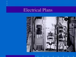
Electrical Plans. Electrical Plans. Displays all of the circuits and systems to be used by the electrical contractor during installation Items to show on plans all outlets all light fixtures connected to switches all switches connected to light fixtures

Electrical Plans
E N D
Presentation Transcript
Electrical Plans • Displays all of the circuits and systems to be used by the electrical contractor during installation • Items to show on plans • all outlets • all light fixtures connected to switches • all switches connected to light fixtures • all miscellaneous and low voltage items • no connection necessary with low voltage items • power panel and electrical meter
Use for class Electrical Plans Methods used to show electrical systems on drawings • 1 Add-on existing plans along with all other symbols, information, and dimensions • common practice on simple floor plans • eliminates extra sheets and simplifies working drawings • sometimes makes drawings difficult to read • 2 Separate sheets for electrical information • common practice on complex floor plans • separates electrical information from other drawing data • requires time to duplicate floor plans unless CAD dwgs • adds more blueprints to set of working drawings
Size and Drafting the Symbols As noted on handout (units given below are full size units taken from the 16 scale) • Size of outlet symbol = 1/8” diameter circle • Size of light fixture symbol = 1/4” diameter circle • Size of fluorescent symbol = 1/8” x 1” (6”x48” real size) • Size of switch symbol = 1/8” lettering • Size of push button symbol = 3/16” square • Size of electrical panel = 3/8”long and fill 1/2 of wall • Size of meter base, etc. = 1/4” square
Outlets • Symbol • as shown on plan • Wall View • finished state • Description • explanation
R H O GD Appliance vs. Voltage and Symbol • Refrigerator 120 volts • Stove 240 volts • Hood 120 volts • Oven 240 volts • Garbage Disposal 120 volts • Dishwasher 120/240 volts
Appliance vs. Voltage and Symbol • Clothes washer 120 volts • Clothes dryer 240 volts • Air Conditioner 120/240 volts • Water heater 240 volts • Furnace 120/240 volts AC WH F
Light Fixtures • Ceiling/Wall fixtures • surface • recessed • Fan (exhaust) • Junction box • Fluorescent fixtures
Switches • Single Switch • 3-way Switch • 4-way Switch • Dimmer Switch • Timer Switch
Electrical Code/Drafting Practice • Duplex convenience outlets (wall plugs) should be a maximum of 12’ apart. Closer spacing is desirable, although economy is a factor. Code reads: “no point along a wall is further than 6’ from an outlet.” • Duplex convenience outlets should be no more than 6’ from a corner • There should be a duplex outlet in any usable wall space over 2’ long • Place a (one) duplex outlet in a hallway
Electrical Code/Drafting Practice Kitchen /Bathroom areas • usable counter space of 12” & greater require an outlet • outlets are required every 48” of counter space (with new code text is in error) • note mounting height for outlets above counter (+44”) • special purpose outlets for garbage disposal, dishwasher, separate oven, and hood • range outlet for electric range • GFI or GFCI protection for any outlets in rooms with a water source.
Switching • Switch symbol and fixture are connected with a dashed line using a irregular curve • Single Switching • 3-Way Switching • 4-Way Switching
Switching a Porch Light +(MOUNTING HEIGHT)
Special Project Elect Plans (50 Points) • Add electrical symbols and all electrical information to your plans: • Foundation plan (3 light +switch, one outlet and special purpose outlet for water heater) • First level floor plan (two exterior WP outlets, lights at all entrances, elect range w/ hood above, garbage disposal, dishwasher outlet, and washer/dryer outlets) • Second level floor plan (exhaust fans in bathrooms, 3-way switch to 1st floor for stair light) • Complete an electrical schedule (10 points) for all the symbols used similar to one shown in Handout
Electrical Symbol Schedule • Purpose of schedule is to identify and describe electrical symbols used in the set of working drawings • Categories • Symbols • Descriptions