Download

1 / 50
550 likes | 748 Views
Understanding dynamics of driven, undamped harmonic oscillators and analyzing forced oscillator behavior with applied forces. Explores amplitudes, phase shifts, resonant frequencies, and mechanical impedance concepts. Detailed solutions provided for oscillation problems.

E N D
Forced oscillator 3rd September 2019
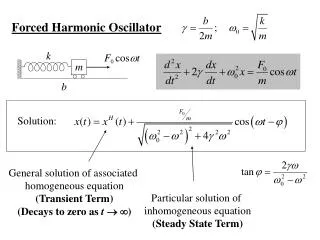
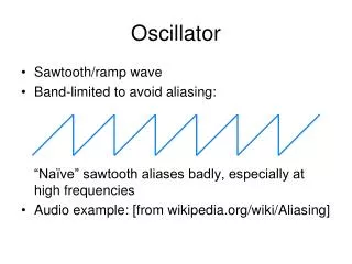
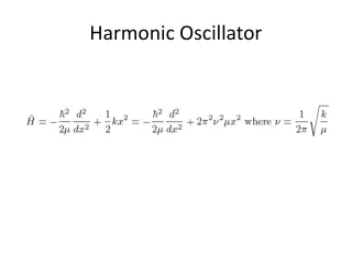
Review :The driven, undamped harmonic oscillator • The equation of motion for harmonically driven, undamped oscillator may be written as • If a general displacement x is given as , the amplitude A is found to be depending on = 0 or and 0 = frequency of free oscillation • The phase shift of “0” indicates that the displacement and the driving force are in phase. • The phase shift of “” indicated that the displacement and the driving force are out of phase by .
(a) the amplitude of a driven oscillator versus with no damping. • (b) The phase lag of the displacement relative to the driving force versus . F0/s
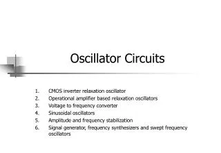
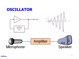
Behavior of the forced oscillator • Consider a mechanical forced oscillator with force F0cost applied to damped oscillator. • The equation of motion is given by • The complete solution for the case is composed of (1) Transient term and (2) Steady state term displacement Applied force steady state Transient + steady state Displacement time http://www.acs.psu.edu/drussell/Demos/SHO/mass-force.html
Driven, damped harmonic oscillator • Generally, the applied force may be written as F0exp(it). • Therefore, the equation of motion becomes • Suppose a general solution of the differential equation is • By substituting the general solution into the equation of motion, we obtain the amplitude A as follows
Description of the steady state term • Therefore, the displacement can be written as Mechanical impedance is a measure of how much a structure resists motion when subjected to a harmonic force. It relates forces with velocities acting on a mechanical system.
Complete information of magnitude and phase of the steady state term • The phase difference between x and F due to the reactive part (m – s/m) of Zm. (2) Extra phase difference gives x lags F by 900 even = 0. • The amplitude of the x is F0/|Zm | 1 2 3
The amplitude of the x • Recall the amplitude from the steady state, • The expression clearly states that the amplitude is a function of the driving frequency, . • The amplitude is still finite even though the driving frequency is equal to the frequency of the free oscillation due to the existence of the r. What is the resonant frequency of the forced oscillator? https://xmdemo.wordpress.com/2014/06/22/040-damping-and-resonance-amplitude/
How to get a resonant frequency of the forced oscillator? • The resonant frequency of the forced oscillator : • The displacement resonance occurs at a frequency slightly less than the free oscillation frequency 0. For a small damping constant r or a large m these two resonances occur at the sample frequency 0. Damping coefficient r influences the resonant frequency.
How to represent the forced oscillation resonant frequency in terms of damping frequency? • Recall the damping freely running damping frequency • The resonant frequency of the forced oscillator : • The resonant frequency of the forced oscillator in terms of the damping frequency
A note on the applied force • Instead of using an exponential form, the applied force as written in terms of cosine or since functions leads to the steady state solution as follows • The value of displacement x resulting from F0cos(t) is • The value of displacement x resulting from F0sin(t) is • Both solutions satisfy the information given in the previous page.
The value of displacement x resulting from F0cos(t) and F0sin(t)
Mechanical Impedance Zm • Mechanical impedance is a measure of how much a structure resists motion when subjected to a harmonic force. It relates forces with velocities acting on a mechanical system. • Mechanical impedance is a complex quantitygiven by • The real part, the mechanical resistance, is independent of frequency. The dissipative forces ( ) are proportional to velocity. • The imaginary part, the mechanical reactance, varies with frequency, becoming zero when equal to the frequency of shm. https://en.wikipedia.org/wiki/Mechanical_impedance
Relation of the velocity and force Provided that the driving force is given as F0cos(t), the velocity becomes • In case of = 0, velocity and force are in phase.. • The amplitude of the velocity is F0/|Zm|, this leads to the definition of the mechanical impedance Zm = F/V
Problem 1 • The equation describes the motion of an undamped simple harmonic oscillator driven by a force of frequency.-Determine the steady state solution and sketch the behavior of the steady state amplitude versus . • -Also find the general solution.
Detailed solution of problem 1 • Using the undetermined method, the steady state solution is given as x = Acost + Bsint • Find dx/dt and d2x/dt2 and substitute into • This gives the steady state solution as • The transient solution can be found from • This gives a general form of the solution to be • Finally, the complete solution becomes
A response of RLC series circuit I Va • The input voltage is equal the sum of the voltage across the inductor, the voltage across the capacitor and the voltage across the resistor. • If Va =V0exp(it), the solution of the above differential equation is given as • Where the electrical impedance Ze is written as To find the solution, we simply compare the electrical system to the mechanical system and substituting m for L, r for R and s for 1/C. http://encyclopedia2.thefreedictionary.com/forced+oscillation
Behavior of velocity v in magnitude versus driving for frequency • The magnitude of the velocity amplitude varies with frequency because |Zm| is frequency dependent. • The impedance is stiffness controlled : at low frequency, s/ dominates. • The impedance is mass controlled: at high frequency, m dominates. • Zero reactance or minimum impedance : Zm = r and velocity and driving force are in phase. This leads to the velocity resonance F0/r . Velocity of forced oscillator versus driving frequency .
Phase behavior of velocity v versus driving force frequency • According to the relationship between the velocity v and force F, • The applied force is • Generally, v lags F by and • Consider 3 situations; > 0, < 0 and = 0. http://www.analyzemath.com/trigonometry/properties.html
Variation of phase angle versus driving force frequency tan /2 Mass controlled = 0 tan = 0 = 0 @ velocity resonance 0 tan- -/2 Stiffness controlled At low frequencies the velocity leads the force ( negative) and at high frequencies the velocity lags the force ( positive).
Behavior of displacement in magnitude versus driving force frequency • Recall the displacement when the driving force is F0cos(t), • Clearly, the amplitude is given as and • The amplitude function suggests that the graph of x vs depends on 3 different ranges of . • What would the amplitude be when 0? • What would the amplitude be when ? • What is the driving frequency at the amplitude resonance? (Next slide!)
The amplitude resonance of the displacement • The displacement resonance occurs when the denominator Zmis a minimum. • This takes place when • The condition gives the driving frequency which gives the displacement resonance. • Therefore, • Thus, the displacement resonance occurs at a frequency slightly less than 0, the frequency of velocity resonance. • Express the driving resonance frequency in terms of damping frequency?
Variation of the displacement of a forced oscillator vs driving force frequency • The maximum displacement at resonance amplitude is given as • Due to (Prove this!) • Therefore, • The amplitude at resonance is kept low by increasing r.
Prove • Consider the amplitude of displacement : • The maximum displacement at resonance amplitude is given as
Phase behavior of displacement versus driving force frequency • Recall the displacement and the driving force • Since the displacement x lags velocity v by ..…………… • Consider when 0, the above condition suggests that x lags/leads/is in phase with F. • Consider when , x lags/leads/is in phase with F. • Consider when = 0, x lags/leads/is in phase with F.
Variation of total phase angle between displacement and driving force vs driving frequency This can be easily explained when considered each condition firstly with the phase difference between v and F and then x and F provided that x and v is always out of phase by
Significance of the two components of the displacement curve (1) • From the displacement • This expression may be rewritten as • Due to and • The displacement is then composed of two terms: resistive fraction and reactive fraction, Reactive term Resistive term
Significance of the two components of the displacement curve (2) Reactive fraction • The amplitude of the reactive fraction may be written as • The amplitude of the resistive fraction may be written as Resistive fraction
Significance of the two components of the displacement curve (3) • This is clear that the reactive fraction becomes zero and resistive fraction is near its maximum at = 0. • However, they combine to give a maximum at , the resonant frequency for amplitude displacement, where
Power supplied to an oscillator by the driving force • To maintain the steady state, the average power supplied by the driving force just equals that being dissipated by the frictional force. Dissipated power by frictional force Average power supplied by the driving force
Variation of Pav with ; Absorption resonance curve • The maximum average power is achieved when cos = 1 and Zm = r. • This corresponds to the case when = 0 and velocity is in phase with applied force. • The sharpness of the peak at resonance is determined by the value of damping constant r. • The curve is known as the absorption curve of the oscillator
The Q-value in terms of the resonance absorption bandwidth • The absorption curve in the previous slide can be used to defined the Q-value as follows • where 1 and 2 are frequencies at which the power supplied • And
The Q-Value as an amplification factor • Note that for high values of Q, the damping constant r is small. • The displacement amplitude curve can be shown in terms of the quality factor Q of the system.
Vibration isolation • Generally, the vibration isolation can be divided into to two basic types ; i.e., (1) displacement isolation and (2) force isolation. • The moving-base model on the left is used in designing isolation to protect the device from motion of its point of attachment (base). • The model on the right is used to protect the point of attachment (ground) from vibration of the mass. http://slideplayer.com/slide/8032841/
Problem on displacement vibration insulation • y = vertical displacement of the base about its rest position. • x = vertical vibration of the floor about its equilibrium position • Requirement :Protect sensitive objects (i.e. heavy base) from vibrating floors and foundations. • Target : The ratio y/A is kept to a minimum. This ratio is known as transmissibility.
Problem on displacement vibration insulation (cont.) • Equation of motion • Suppose y > x; • Suppose • Determine the derivatives of y and x and substitute in the equation of motion. • This ends up in terms of the magnitude ratio as follows,
Physical meaning of the ratio |y/A| • What does it mean if the magnitude ratio is greater than 1? • Under the condition, this is found that or
DisplacementTransmissibility |y/A| • The displacement vibration isolator will generally operate at the mass controlled end of the frequency spectrum and the resonant frequency is designed to be lower than the range of frequencies likely to be met. http://machinedesign.com/archive/shaking-vibration-models
Analysis of the displacement transmissibility • From the displacement transmissibility the object vibrates less than the supporting surface of vibrating frequency if vibration frequency (region of isolation). • Lower-stiffness vibration isolators decrease the natural frequency 0 and transmit less vibration to the objectfor almost driving frequencies. • The increasing isolator damping reduces an object’s vibration amplitude at by lessens isolation at (region of amplification). http://www.novibration.com/isoselectguide.htm
Displacement transmissibility in terms of damping ratio • By definition, the damping ratio is given as the ratio of the damping factor to the critical damping factor, • This leads to • Therefore, the transmissibility in terms of is written as
Problem : Effect of speed on the amplitude of car vibration • Given • (1) car speed = 20 km/hr • (2) car mass = 1007 kg (3) stiffness s = 4 x 10⁴ N/m • (4) damping constant r = 2000 Ns/m • Determine the amplitude response of the car to the vibrating road surface by considering the surface disturbance in the form of a sinusoidal input. y(t) 20 km/hr r s http://www.slideshare.net/SondiponAdhikari/base-excitation-of-dynamic-systems
Force vibration isolation • The vibration source is mounted on isolator composed of a spring with stiffness s and a damper with damping constant r . • The mass is disturbed by a force F(t). • What is the force transmissibility for isolating the source of vibration? s r http://slideplayer.com/slide/8032841/
Force vibration isolation (cont.) • Equation of motion of mass m is given by • The solution as the displacement is written as • This can be written in terms of , and 0 as
Force vibration isolation (cont.) • The response of the supporting base is due to the force combination of spring with stiffness s and damper with damping constant r . • By substituting x from the previous slide and determine the force transmissibility, A = vibrating amplitude of the base
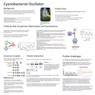
Force transmissibility curve http://www.kaztechnologies.com/faq/
Homework #2 (cont.) • 2.