Download
1 / 89
1.16k likes | 2.2k Views
Technische Universität Dresden. Peter Krebs. Department of Hydro Science, Institute for Urban Water Management. Urban Water Systems. 10 Urban Drainage. 10.1 Rain characterisation 10.2 Rain-runoff process 10.3 Sewer structure elements 10.4 Stormwater concepts. 10 Urban drainage.

E N D
Technische Universität Dresden Peter Krebs Department of Hydro Science, Institute for Urban Water Management Urban Water Systems 10 Urban Drainage 10.1 Rain characterisation 10.2 Rain-runoff process 10.3 Sewer structure elements 10.4 Stormwater concepts 10 Urban drainage
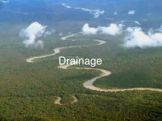
10 Urban drainage 10.1 Rain characterisation 10 Urban drainage
Rain-runoff process Rain Runoff Not predictable Can be analysed statistically Affected by systematic changes Cannot be analysed statistically Models Measurements Dimensioning 10 Urban drainage
Significance of stormwater • Stormwater runoff decisive for pipe diameter • Contaminated after surface runoff • Sewage overflow due to stormwater runoff • Erosion of sewer sediments • WWTP operation is disturbed for longer than the rain duration 10 Urban drainage
Rain measurement Syphon Weighing Tipping bucket 10 Urban drainage
Description of rain events Intense event Long duration event From Dyck and Peschke (1989) 10 Urban drainage
Rain measurement Defined opening area of 200 cm2 Normalised shape in vertical section Measurement error depending on Wind velocity field Rain or snow Wind protection shield 10 Urban drainage
Description of rain (precipitation) Rain height hR in mm Rain duration tR in min Rain intensity in mm/min, l/(s·ha), m/s Rain intensity r Area = hR Block rain Time t tR 10 Urban drainage
Resolution in time r (l/(s·ha)) r (l/(s·ha)) Time (min) Time (min) 10 Urban drainage
Resolution in time Runoff 10 Urban drainage
Resolution in time retention volume Retention volume in m3 Date of rain event t = 5 min t = 10 min 29.08.1964 1890 1886 07.07.1965 1792 1772 17.07.1963 1232 1225 19.05.1964 1089 1075 From Krejci et al. (1994) 10 Urban drainage
Resolution in space 10 Urban drainage
Assignment of rain gauges to sub-catchments Thiessen-Polygon (from Dracos, 1980) 10 Urban drainage
Extreme value frequency (Reinhold, 1940) 10 Urban drainage
Reference rain intensity r15(1) in l/(s·ha) Baden-Baden 120 Berlin 94 Bonn 108 Bremen 108 Dortmund 120 Dresden 102 Essen 96 Flensburg 100 Frankfurt/Main 120 Garmisch-Patenkirchen 200 Göttingen 98 Hamburg 99 Hannover 100 Köln 97 Konstanz 150 Krefeld 112 Lübeck 106 Mainz 117 München 135 Münster 100 Oldenburg 108 Osnabrück 150 Passau 123 Saarland 135 Stuttgart 126 Tübingen 200 Ulm (Donau) 140 Wetzlar 122 Wilhelmshaven 85 Wolfsburg 112 10 Urban drainage
70 = 30 min t R (mm) 60 j h 50 s 40 s h 30 Pm Maximum rain depth 20 10 0 1 2 3 4 5 6 7 8 9 10 11 12 13 14 15 16 17 18 19 20 Year j Frequency analysis z-years event 10 Urban drainage
Frequency analysis z-years event Mean value Standard deviation Frequency factor fK = f (duration of data collection, frequency) from tables 10 Urban drainage
Return period for sewer design Catchment Return period (a) Mixed structures 1 – 2 City centre, important industry area 1 – 5 Streets, not in cities areas 1 5 – 20 Street underpass, underground 10 Urban drainage
Historical rain events Significance Critical impacts to receiving waters Less significance for sewer design Prerequisites for data collection Measuring time period Resolution in time Resolution in space Time synchronisation Data bank systems 10 Urban drainage
10 Urban drainage 10.2 Rain-runoff process 10 Urban drainage
Peak runoff factor r·A QR rmax·A QP Runoff duration Rain duration 10 Urban drainage
Peak runoff factor Pand coefficient P 10 Urban drainage
Peak runoff factor = f(rain intensity r, slope J) 1 0,9 4% < < 10% J (-) 0,8 P y 0,7 0,6 0,5 r = 225 (l/(s·ha)) r = 180 (l/(s·ha)) 0,4 Peak runoff factor r = 130 (l/(s·ha)) 0,3 r = 100 (l/(s·ha)) 0,2 0,1 0 0 0,2 0,4 0,6 0,8 1 Impervious area (-) 10 Urban drainage
Dry- and wet-weather runoff Population density e = 100 Inh/ha DrWa-consumption q = 100 l/(Inh·d) Rain intensity r15(1) = 100 l/(s·ha) Peak runoff factor P = 0,4 DW WW 10 Urban drainage
Rain-runoff-process in two steps Runoff production r·A Q Runoff concentration Time 10 Urban drainage
Losses and runoff production Permanent losses Infiltration losses Wetting losses Depression storage Rain intensity Runoff Rain duration 10 Urban drainage
Pervious area 10 Urban drainage
Surface runoff and infiltration 10 Urban drainage
Surface classification 10 Urban drainage
Rain duration to produce maximum runoff ra Qa tR< tC tR tC rb Qb A tR= tC tC 2 tC 10 Urban drainage
Rain duration to produce maximum runoff A Qc rc tR> tC tR tR+tC Concentration time = surface runoff time + flow time in sewer 10 Urban drainage
Assumption of decisive rain duration with a lack of information 10 Urban drainage
Rationale method 3 1 2 4 5 6 for Point 3 for Point 4 Iteration with effective concentration time tC 10 Urban drainage
Rationale method 10 Urban drainage
Application of rain-runoff models Rationale method Maximum flow rate Extreme rain event as input Dimensioning of sewer cross section Detailed numerical simulationen Flow as a function of time at every point in the system Measured rain events as input Evaluation of functionality of sewer system Optimisation of operation and control Estimation of impact to receiving water 10 Urban drainage
10 Urban drainage 10.3 Sewer structure elements 10 Urban drainage
Combined system Rain water Groundwater , Drainage, … Domestic and industrial sewage clean polluted Comb syst CSO WWTP Rain water Groundwater , Drainage, … Domestic and industrial sewage clean polluted Comb syst Infiltration CSO WWTP Groundwater aquifer 10 Urban drainage
Combined system 10 Urban drainage
Combined system Cross section through street underground Gully Manhole House connection No access for rehabilitation (DIN 1998) 10 Urban drainage
Separate system Rain water Groundwater, drainage, … Domestic and industrial sewage clean polluted Storm sewer Sewage sewer Rainwater treatment WWTP Rain water Groundwater, drainage, … Domestic and industrial sewage clean polluted Storm sewer Sewage sewer Infiltration Rainwater treatment WWTP Groundwater aquifer 10 Urban drainage
Separate system 10 Urban drainage
Separate system Cross section through street underground Manholes Gully Street water Roof water House connection: sewage DIN (1998) 10 Urban drainage
Comparison of combined and separate system Target Combined system Separate system WWTP • Distinct load variation • Theoretically relatively homogeneous loading re. both flow and load • Storage tanks needed • Increased design requirements • CSO includes part of the sewage • Stormwater discharge untreated Receiving water • No sewage directly to river • Time delay before combined water is discharged • No retention, quicker discharge Sewer system • Lower contruction costs • 2 sewers, more expensive • More space requirement in the ground • Space requirements in the region of retention tanks • Not retention tanks needed 10 Urban drainage
Comparison of combined and separate system Target Combined system Separate system Sediments • Frequent self-flushing • More susceptible to sedimentation • Rel. small slope needed • Higher slope needed • Less cleaning required • More cleaning required Maintenance • Increased total sewer length • Better air exchange House connection • No mis-connections • Mis-connections • Backwater effect to cellars • No backwater effects Pumping • If possible only sewage has to be pumped • High pumping performance needed which is used only seldomly 10 Urban drainage
Sewer cross sections 10 Urban drainage
„Other“ sewer profile 10 Urban drainage
Elements of stormwater treatment Function Element Applied in Overflow • CSO structure Combined system • Sewer overflow • First flush tank Combined water retention Combined system • Flow-through tank • Combined tank • Storage channel Stormwater treatment Separate system Stormwater retention Comb., sep. system Pollutants retention • Sewage retention tank Upstream comb. Syst. • Gully Comb., sep. system 10 Urban drainage
Operation of combined water oberflow structures River Weak rain CWRTR SO CSO WWTP moderate CWRTR rain SO CSO WWTP intense CWRTR CWRT combined water retention tank WWTP wastewater treatment plant SO sewer overflow CSO CSO structure rain SO CSO WWTP Extreme - CWRTR event SO CSO WWTP 10 Urban drainage
Overflow structure with side weir Overflow at Throttle flow Mixing ratio resp. with cDW > 600 mg/l 10 Urban drainage
„Leaping Weir“, bottom outlet 10 Urban drainage