Precision Measurement and Analysis Features at Johns Hopkins APL
720 likes | 738 Views
Discover the measure features, feature relations, and datum analysis features at Johns Hopkins University Applied Physics Laboratory (APL), with focus on space science and technology. Dive into surface area analysis and sensitivity studies with detailed case studies and hands-on examples.

Precision Measurement and Analysis Features at Johns Hopkins APL
E N D
Presentation Transcript
Measure Features, Feature Relations and Datum Analysis Features Ron Thellen Johns Hopkins UniversityApplied Physics Laboratory
APL … At a Glance • University-Based Applied Research & Development Laboratory • Focus on National Security • Major efforts in Space Science & Technology • Partner in Johns Hopkins Commitment to Education & Medicine • 4000 Employees
APL … Recent Space Science Examples • New Horizons • 10 Year, 3 Billion Mile Journeyto Pluto and beyond • STEREO • Twin satellites capturingstereo images of the sun • MESSENGER • 1st spacecraft toorbit Mercury
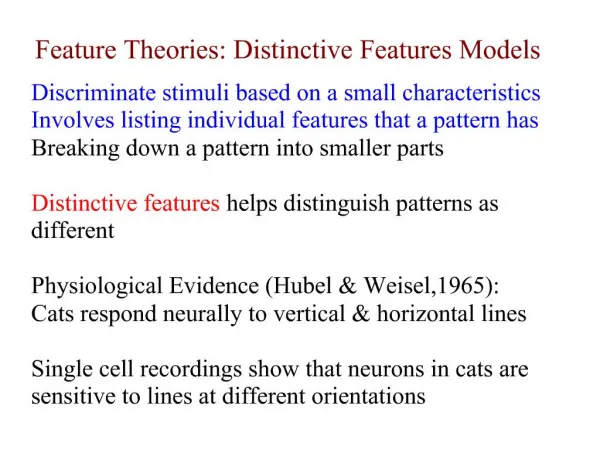
Topics of Discussion • Measure Features • Distance • Angle • Area • Feature Relations and Feature Parameters • UDA (User Defined Analysis) • Construction Groups • Field Datum Points • Sensitivity Studies
Review Two Case Studies • Surface Area Analysis • Measure Features • Feature Relations/Parameters • Sensitivity Analysis • Field of View Study • Measure Features • UDAs • Field Datum Points • Construction Groups
Surface Area Analysis Problem • Analyze the change in area of multiple surfaces as the shape of the model changes. • Graphically capture the resulting changes to the model. • Pass the results to Excel for further study.
Surface Area Analysis Initial Conditions • Given a column of materialcontaining spherical cavities • Monitor surface area of • Flat green surface • Red spherical cavity • Blue spherical cavity • Additional cavities…
Surface Area Analysis Further Conditions • As column height decreases • Green plane contacts red sphere • At that point the red sphere begins increasing in size • Eventually the red sphere contacts the blue sphere • At that point the blue sphere begins increasing in size
Surface Area Analysis Start the Model • DTM1 is offset from TOP • DTM2 is offset from DTM1 • Extrude 1 is sketched onTOP and extruded to DTM2
Surface Area Analysis Build 1st Sphere • Sketch Datum Curve for initial sphere size • Create CS0 at top of curve • Used to measure flat green surface location relative to initial sphere size and location • Create Distance Measure Feature • Create spherical cut • Do not use sketched datumcurve above • Group features
Surface Area Analysis Build Additional Spheres • Repeat steps in previous slide • For each sphere’s Distance Measure Feature • Measure from its grouped CSYS to the sphere above
Surface Area Analysis Create Area Measures • Create Area Measure Features for • Flat green plane • Red sphere • Blue sphere • Yellow sphere • Create Annotation to display measure results
Measure Features An Overview • Analysis Measure … • Distance • Angle • Area • Common to all… • Select features to measure • Select type of measure (Quick, Saved or Feature) • Assign name (for Saved and Feature) • For Feature types • Regenerate status and optional Feature Parameters and Datum Features
Measure Features Select measure entities From – To Returns distance Select optional projection reference Returns dx, dy, dzin addition to distance Change type from Quick to Feature Assign appropriate name Distance Example
Measure Features Select Feature tab Select Regenerate type Always, Read Only, Design Study Select optional featureparameters to create DISTANCE_Y is of interestin this case Select optional datumfeatures to create Distance Example (cont.)
Feature Relations and Parameters • Tools Relations (includes parameters) or… • Tools Parameters • Relations and Parameters can apply to • Part (default) • Feature • Other…
Feature Parameters • Change “Look In” from Part to Feature • Select the Feature in • Model Tree or… • In model • Select Add Parameter • Assign Name and Valueto the Parameter • This is only an example.It is not used in this study. • As shown earlier, Feature Parameters can also be created as part of a Measure Feature
Feature Relations • Change “Look In” from Part to Feature • Select the Feature in • Model Tree or… • In model • Enter relation • This Feature Relationis what causes thesphere radius toincrease • Create an equivalent relation for each sphere
Relation in Detail What does it say? • distance_y • is the Feature Parameter created while defining the Measure Feature • FID_ • Feature ID • DTM2_TO_CS0_DISTANCE • The name of the Measure Feature
Relation in Detail If the feature parameter named “distance_y”,in the (:) feature with the id (FID_)named “DTM2_TO_CS0_DISTANCE”is less than (<) 0 Dimension d14 is assigned the value of the Part parameter named “pore_start_radius” minus the value of the feature parameter named… But what does it say?
Feature Relations Shortcut In the Relations editor enter the starting text Press the Insert Parameter Name from List button
Feature Relations Shortcut (cont.) In the Relations editor enter the starting text Press the Insert Parameter Name from List button In the Select Parameter dialog, change to Feature and select the Measure Feature in the model tree
Feature Relations Shortcut (cont.) In the Relations editor enter the starting text Press the Insert Parameter Name from List button In the Select Parameter dialog, change to Feature and select the Measure Feature in the model tree Select the parameter and press Insert Selected The feature parameter is added to the relation
Surface Area Analysis Back to the Model • We could edit the offset value of DTM2 manually to exercise our model…but where’s the fun in that?
Sensitivity Analysis Analysis Sensitivity Analysis… Used to examine how sensitive your model is to dimensional changes Some initial setup options Preferences Animate Model (Yes!) Default range Set’s the default range for selected dimension you will adjust (I usually skip this and adjust the range manually)
Sensitivity Analysis The Dialog • Set Options • Assign Study Name • Select Variable Dimension • DTM2 offset dim • Set Variable Range • Select Parameter to plot • One of the Area MeasureFeature parameters • Set the # of Steps • More steps = finer analysis • Compute
Sensitivity Analysis The Displayed Results
Sensitivity Analysis The Graphed Results ??? SPR 1450730
Sensitivity Analysis The Graphed Results (cont.) 2 3 1 2 3 4 1 ??? 4
Surface Area Analysis Utilized… Measure Features Feature Relations/Parameters Sensitivity Analysis Analyzed the change in area of multiple surfaces as the shape of the model changed. Graphically captured the resulting changes to the model. Passed the results to Excel for further study. Summary
Review Two Case Studies Surface Area Analysis Measure Features Feature Relations/Parameters Sensitivity Analysis Field of View Study Measure Features Construction Groups Field Datum Points UDAs
Field of View Study Determine the reduction in a field of view that is caused by an obstruction Determine % reduction in the field of view Problem
Field of View Study Field of View origin is a point Assumption
Pro/PHOTORENDER Analogy Field of View origin = Point light source Obstructed volume = Shadow cast by obstruction
Field of View Study Half sphere in this example Assemble into assembly where we will view the results of the study Assign appropriate references Csys to csys in this example (focal point) Create Field of View Model
Field of View Study In order to determine % reduction in Field of View Create an Area Measure before we create features that will cut out the obstructed volume(Analysis Measure Area) Create Area Measure Feature
Field of View Study Used for subsequent feature creation Focal Point Axis of Rotation Projection Plane (offset from sphere surface) Create Additional Construction Geometry
Field of View Study Insert Shared Data Copy Geometry… Only the surface quilt of one part was selected (in this case) Copy Obstruction Geometry
Field of View Study Create Datum Plane Through Axis of Rotation Offset (at an angle) from existing plane (FRONT) Intersect Copied Geometry
Field of View Study Create Datum Plane Through Axis of Rotation Offset (at an angle) from existing plane (FRONT) Intersect Datum Plane with Copied Geometry Edit Intersect… Intersect Copied Geometry (cont.)
Construction Group A Construction Group… Includes geometry features (usually Datum Features) Can include a Field Datum Point Must include an Analysis Feature (and it must be the last feature in a Construction Group, otherwise it is just a Group) Used by User Defined Analysis (UDA) If the first feature is a Field Datum Point, the Analysis Feature measure can be solved across the entire length of the curve or over the entire surface it is created on (the domain)
Construction Group (cont.) Do not use the features in a Construction Group for subsequent modeling activities After creating the Construction Group, suppress it It will still be selectable for UDA purposes
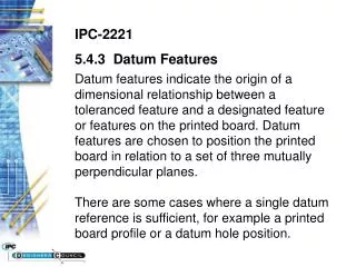
Field Datum Point Insert Model Datum Point Field… or A Field Datum Point… Is a dimensionless Datum Point Exists within the domain of a Datum Curve Surface
Field of View Study Create the Field Datum Point on the intersect curve created previously Field Datum Point (for Construction Group)
Field of View Study Create a Datum Curve from the Focal Point to the Field Datum Point Datum Axis (for Construction Group)
Field of View Study Create a Measure Angle Feature to measure the angle between the Axis of Rotation and the Datum Axis just created. Use the Datum Plane previously created as your projection plane. Measure Angle Feature (for Constr. Group)
Field of View Study Pay close attention to the blue measure arrows. Use the yellow flip arrows if necessary. Set Plot range to +/-180 Measure Angle Feature (cont.) Viewed looking at DTM1(the projection reference)
Field of View Study Create the PROJ_ANGLE parameter Set Regenerate to Always Measure Angle Feature (cont.)
Field of View Study Select the features to include in the Construction Group Group the features Suppress the Group Create the Construction Group
User Defined Analysis (UDA) A UDA is a specific type of Datum Analysis Feature Insert Model Datum Analysis… or Used to create measures or analyses beyond those available in the Analysis menu