
Capacitors: Types and Functions
E N D
Presentation Transcript
DISCLAIMER & USAGE • This material is based upon work supported by the National Science Foundation's Advanced Technological Education Program under Grant No. 1801177. • Any opinions, findings, and conclusions or recommendations expressed in this material are those of the author(s) and do not necessarily reflect the views of the National Science Foundation. 2
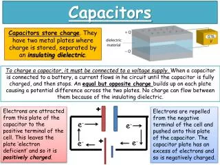
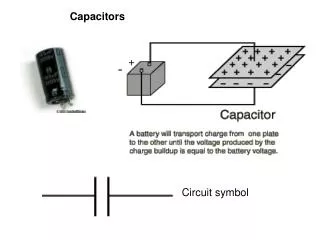
The Capacitor Plates • There are three classifications of capacitors: • Non-polarized • Electrolytic • Variable Dielectric Schematic Symbol • A component that has the ability to store an electrical charge. • Constructed from two plates separated by a non-conducting dielectric. • Dielectric – A type of electrical insulator. • Different than a battery by its construction. A battery stores electrical charge in chemical bonds.
How it works • When the voltage source is disconnected, the ions remain on the plates. • The ions that remain on the plates create a potential difference, or voltage, that may be used at a later time just as a battery would. • When a voltage source is first applied to a capacitor: • Electrons flow from negative terminal to the bottom plate of capacitor. • These electrons cause a build up of negative ions. • The positive terminal attracts electrons causing an excess of positive ions on the top plate.
The Non-polarized Capacitor Schematic Symbols • General purpose capacitors used to: • Isolate one circuit from another • Block unwanted AC signals • Produce wave shapes • Has no polarity (i.e. like a resistor, can be hooked up either way). • Curved line in the schematic symbol denotes the lower voltage side of the circuit; does not indicate a particular polarity.
The Electrolytic Capacitor Schematic Symbols Named because of the particular process used in manufacturing of capacitor. Main use is filtering unwanted AC signals in DC circuits. Does have polarity. Denoted by + sign on schematic. Polarity should be marked or the long wire lead indicates positive side.
The Variable Capacitor Schematic Symbols The schematic symbol contains a crossing arrow. The variable capacitor does as the name implies. Allows the capacitance to be varied or adjusted. Non-polarized and electrolytic capacitors are sometimes referred to as fixed capacitor by their inability to be adjusted. Transmitters and receivers commonly used variable capacitors.