Download
1 / 12
120 likes | 146 Views
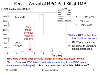
This analysis compares the arrival time of the RPC Pad Bit at the TMB Ring +1/2 with the CSC trigger primitive time to determine consistency. It also includes estimates for CLCT pretrigger latency and RPC cable length.

E N D
Recall: Arrival of RPC Pad Bit at TMB Ring +1/2 • Note: for Ring+1/3 • Avg = 7.3 • RMS = 0.79 CSC trigger primitive found by this time • Width in RPC arrival time has contributions from: • CLCT pretrigger jitter • Chamber-to-chamber timing differences CLCT pretrigger Time (bx) • RPC data arrives after the CSC trigger primitive has been formed • To do:Compare (CSC latency estimate + cable lengths) to (RPC latency estimate + cable lengths)… Are they consistent with this distribution? G. Rakness (UCLA)
CLCT Pretrigger Latency Estimate Starting from Jay’s spreadsheet, using current TMB documentation, removing (common) Time-Of-Flight • CFEB drift delay to last hit of 6 layers expected = 3.0 • CMS setting assumed, CLCT lose ~10% of 6th hits, lower thresholds help • Signal prop. on strips and CFEB cables = 0.8 • Value is probably from Korytov • Preamp latency = 1.0 • Buckeye latency • Comparator delay for peaking time = 3.0 • Should study comparator and CLCT efficiency vs. this value • Comparator latency, clock to first triad = 2.0 • CFEB mux to triads = 1.5 • Average Skew Clear delay for ME+1/2-3 CSC’s = 2.1 • Computed based on cable lengths + revision type • TMB triad demux/synchronization = 0.0 • TMB triad decoding to ½-strips = 2.0 • TMB one-shots/pattern-matching = 2.0 • CLCT pretrigger = 1.0 Cumulative total = 18.4 bx G. Rakness (UCLA)
RPC-cable length + RAT latency • Average value of RPCRAT cable length, assuming 5.0 nsec/m = 1.7 bx • Used calculation of latency from receipt of RPC data to insertion in FIFO = 6 bx G. Rakness (UCLA)
Simple Sums The value of the latency in the RPC endcap Link Board (LB) path relative to the CLCT pretrigger is related by… (RPC latency + RPC-LB cable length + LB latency)+ (RPC-RAT cable length + RAT latency) = position_of_RPC_data_in_FIFO + CLCT pretrigger latency From the previous slides: (RPC latency + RPC-LB cable length + LB latency) = 15.7 What do our RPC colleagues say about this? G. Rakness (UCLA)
RPC Response… From a latency review in Nov. 2007, the RPC estimates: • 1 = chambers + FEBs • 4 = cables (max) is this right for these endcap LinkBoards? • 3 = synchronizer this is not needed for CSC. Is it possible to brake this out? • 2 = coder • 1 = slave-master transmission • 0 = data delay • 2 = muxer • 13 = TOTAL This is not consistent with my estimate… • RPC colleagues are planning to measure their firmware latency on a scope G. Rakness (UCLA)
Low Voltage Control Low Voltage control devices = Maratons and Peripheral Crates (ELMB) Recall: loss of communication to the Maraton means we have to cycle power on the Maraton to restore communication… • Using multimeter and scope to look at CANbus lines in experiment, we see: • Maraton signals do not look too bad • ELMB signals do not look too good • Some noise on both—signal analysis is differential, so it may or may not be a problem… G. Rakness (UCLA)
ELMB digging • CANbus ground was not tied to detector ground • 6V difference between CANbus ground and CANbus tranceiver ground probably is a problem… • Have connected CANbus ground to detector ground on ¼ of detector... Need to see if it makes a difference… • 50 resistance through 27 AWG ethernet cables • Difference in High – Low = 2.0V at beginning of chain • High – Low = 1.0V at end of chain… • CANbus spec = 3.5 – 0.9 Need to see if we see a problem from one end of the chain to another… G. Rakness (UCLA)
Final stuff on CANbus • Evaldas Juska is working on a “handshake” program to write/read register on each component • Had it working on Maratons… He saw the following types of errors after several hours… • One Maraton who never responded • Several Maratons with no errors… • One Maraton who had one error • One Maraton who quit responding at 3:15am • All Maratons stopped responding when Petr messed around with the chain… • Am pushing him to get it working on ELMB’s… • I want to be able to run this overnight on Thursday night so we can get an overview of our current status • Paul Padley said, if positive progress isn’t shown by early March (when he is here), there will be a session of “lock experts in the room, don’t let them out until they come up with a solution” G. Rakness (UCLA)
What else? • Configuration database implementation waiting for ability as we had with xml files, that is… • Display results • Change values (as done with perl scripts) • Presentation to be given by Angela Brett at the online software meeting this upcoming Tuesday… • Started working at 904 to implement TMB-ALCT communication software • N.B. only have an ALCT 672 there… • Current HEAD version of online software doesn’t even compile =:-/ G. Rakness (UCLA)
To do • Get TMB + ALCT test firmware working • at 904 • At point 5 on chambers with problems • Push CANbus studies at point 5 • Combine firmware version check into configuration check moving towards a single push-button check of all configuration… G. Rakness (UCLA)
Backup G. Rakness (UCLA)
2 flight (max) 1 chambers + FEBs 4 cables (max) LB 3 synchronizer 2 coder 1 slave-master transmission 0 data delay 8 2 Muxer 2 GOL 19 fibber 2 TLK 3 Opto 6 Opto - PAC transmission 11 PAC algorithm 6 PAC - TB Sorter transmission 4 TB Sorter algorithm 6 TB Sorter - TC Sorter transmission 3 TC Sorter algorithm 6 TC - HSB transmission 4 Half Sorter algorithm 6 HSB - FSB transmission 3 Final Sorter algorithm 96 Total RPC trigger latency • In current version of firmwares additional latches are inserted to speed up the compilation total latency ~96 BX. • After firmware optimization it should be possible to reduce the latency to ~ 80 BX Optimization: ~ -10 BXs (2 BX x 5) on transmissions ~ -5 BXs on algorithms Karol Buńkowski, Warsaw University