Download
1 / 37
370 likes | 403 Views
Learn about architectural technology, new materials, project management practices, and building design integration. Develop expertise in construction technologies and project execution for efficient results. Architectural management ensures cost-effectiveness and quality.

E N D
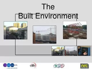
BUILT ENVIRONMENT COURSE LESSON - (3)
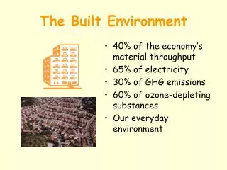
Introduction Architectural Technology and Management Architectural technology, or building technology, is the application of technology to the design of buildings. It is a component of architecture and building engineering and is sometimes viewed as a distinct discipline or sub-category. New materials and technologies generated new design challenges and construction methods throughout the evolution of building, especially since the advent of industrialisation in the 19th century. Architectural technology is related to the different elements of a building and their interactions, and is closely aligned with advances in building science. Architectural technology can be summarised as the "technical design and expertise used in the application and integration of construction technologies in the building design process. or as "The ability to analyse, synthesise and evaluate building design factors in order to produce efficient and effective technical design solutions which satisfy performance, production and procurement criteria."
Practice of Architectural Technology Architectural technology is a discipline that spans architecture, building science and engineering. It is practiced by architects, architectural technologists, structural engineers, architectural / building engineers and others who develop the design / concept into a buildable reality. Specialist manufacturers who develop products used to construct buildings, are also involved in the discipline. Architectural technology is informed by both practical constraints, and building regulations, as well as standards relating to safety, environmental performance, fire resistance, etc. In practice, architectural technology is developed, understood and integrated into a building by producing architectural drawings and schedules. Computer technology is now used on all but the simplest building types: in the twentieth century the use of computer aided design (CAD) became mainstream, allowing for highly accurate drawings that can be shared electronically, so that for example the architectural plans can be used as the basis for designing electrical and air handling services.As the design develops, that information can be shared with the whole design team. That process is currently taken to a logical conclusion with the widespread use of Building Information Modelling (BIM), which uses a three dimensional model of the building, created with input from all the disciplines to build up an integrated design.
Architectural Management Architectural management falls into two distinct parts, office management and project management. Office management provides an overall framework within which individual projects are commissioned, designed and completed. Both parts have the same objectives but are typically addressed by separate management systems. Office management involves the allocation and financing of resources, principally premises, trained staff and computer systems, and on establishing and charging appropriate fees for the services rendered. Project management focuses on timescales, developing a design from initial concept to working drawings, and managing the construction process The essence of architectural management is to ensure that work on a project is cost-effective, to achieve a balance between profitability and design quality.
Project Management Project management is the practice of initiating, planning, executing, controlling, and closing the work of a team to achieve specific goals and meet specific success criteria at the specified time. A project is a temporary endeavour designed to produce a unique product, service or result with a defined beginning and end (usually time-constrained, and often constrained by funding or staffing) undertaken to meet unique goals and objectives, typically to bring about beneficial change or added value. The temporary nature of projects stands in contrast with business as usual (or operations), which are repetitive, permanent, or semi-permanent functional activities to produce products or services. In practice, the management of such distinct production approaches requires the development of distinct technical skills and management strategies.
Project Management – continue The primary challenge of project management is to achieve all of the project goals within the given constraints. This information is usually described in project documentation, created at the beginning of the development process. The primary constraints are scope, time, quality and budget. The secondary — and more ambitious — challenge is to optimize the allocation of necessary inputs and apply them to meet pre-defined objectives. The object of project management is to produce a complete project which complies with the client's objectives. In many cases the object of project management is also to shape or reform the client's brief in order to feasibly be able to address the client's objectives. Once the client's objectives are clearly established they should influence all decisions made by other people involved in the project - for example project managers, designers, contractors and sub-contractors. Ill-defined or too tightly prescribed project management objectives are detrimental to decision making.
LESSON (3) – Technical Drafting Introduction To Technical Drawing B. Drafting Equipment C. Line Drawing D. Free Hand Lettering E. Title Block
A. TECHNICAL DRAFTING & DRAFTING EQUIPMENT Technical drafting or drawing, is the act and discipline of composing drawings that visually communicate how something functions or is to be constructed. Technical Drawings is in fact the construction drawings and has to be well organized in sequences to ensure easy reference. The annotation must be cleared with all necessary information to be indicated in the drawings, with cross references; as the drawing may be congested when annotating directly on the drawings, legend with symbol and description is important to be provided. A full set of drawings can be quite an intimidating sight. Even for small projects a full set of drawings can easily contain over 50 pieces individual sheets.
Technical drawing also apply to various sectors of professional body in the industry, Architecture, Landscape, Structure, Mechanical & Electrical, other relevant specialists and suppliers, manufacturers etc. Each individual will have their own systems and organizations in the drawing format for producing the technical drawings. Technical drawings is very important for construction and it is also form part of the specification in any tender documents. Technical drawing usually fall on stage (3) of the projects, once the preliminary design, final conceptual design and submission drawings are cleared in principle by the Authority, if required. The drafter or draughtsman will have to prepare all these technical drawings and specification information. Technical drawings are basically consists of the following in sequences:
Architecture Working Drawings Plan & Section Subsequently, it apply the same for the Plan and Section drawings. Section Layout Plan Fig.(A) Sectional Detail Fig.(B)
Architectural Working / Construction Drawings – Elevation Architectural working drawings for elevation are usually annotate with necessary information finishes materials for the roof, walls, doors and indicate the type of windows. Most of the case, legend is provided with list of finishes code numbers. This will reduce the intimate / congestion of the drawings. It also easier for viewer. Elevation Elevation Fig.(D) Fig. (C)
Architecture Working Drawings – Enlarge & Sectional Detail Fig.(E) - Enlarge Detail Fig.(F) - Sectional Detail Fig.(G) - Sectional Detail
Architecture Working Drawing – Blown-up Detail Drawings Fig.(H) , (I) & (J) Blown–Up Details Fig.(H) Fig.(I) Fig.(J)
Architectural drawings are made according to a set of convention, which include particular views:- Site Plan Floor Plan Elevation Section Construction/Detailing Drawing. Every drawings must consist of the following information within the standard drawings format & sizes, (AO, A1, A2 and/or A3 if the project is small). Drawing Title Block Unit of measurement Scale Annotation Cross references
B. EQUIPMENT, TOOLS AND MATERIALS The following essential media and tool use for the drawings are:- • The Drawing Board. (Slightly bigger than A3– A1 size) • Various pencil grading (H or F, HB & 2 or 3HB). • Various signed pen or felt pen and pointed pen. (Refine pen and thick felt pen) • Erasers and Blanco, (soft is for erasing of pencil line & hard is for erasing the scratch pen line) • Erasing Shield. • Compass. • T-square or adjustable T-square. • Set square. (30/60 degrees and 45 degrees or adjustable). • Protractor. • Scale ruler. (1: 100, 50, 25, 20, 10) commonly used for small project. • Template – (Sanitary Fittings/Furniture and Circle etc. Square & rectangle may not require.) • Various types of paper etc. (normal white paper, butter paper and tracing paper – in sheet or roll form) • Lettering Guide
1. Thick draft paper Sandwich or butter paper -like, thin translucent sheet of paper. Manufactured in different strengths, the surface may be slightly polished. This paper also wrinkles upon wetting. Suitable for pencil and felt tipped pens, and with limitations for technical pens. An eraser can be used for pencil lines. Ink is difficult to erase without damage. 2. Tracing paper sheet or roll. Polished sandwich paper -like, translucent thick paper, which comes in different strengths. Wrinkles upon wetting. Suitable for both graphite pencils and technical pens. An eraser or sharp scraper tool is used for corrections.
The Fundamental Of Drafting/Drawings Understanding the fundamental of drafting/drawings using the manual tools and how line works could transfer into the paper on the visual communication, the perceiving and perception for architectural technical drawings.
C. Line Drawings “LINE” Line weight is simply how thick or thin the line on the page appeared. Line weight in drawings actually exploits a natural phenomenon known as atmospheric perspective where objects are closer to us are rendered in higher contrast and appear darker to our eye. Line creates the following Texture make the 2-dimensional (flat drawings) and 3-dimensional drawings with variation, depth and clarity. It capture the visual impact aesthetically and direct the eyes for easier understanding. Variety of lines thin & thickness Dots to create texture similar to line. Variety of Shadings that create the value of tone. Shadows to create the depth of an object. Line drawing is very important to any drawings needed to express and as a visual communication tools. In fact to become a good artist, one must master the skill of line drawing for sketching diagrams or objects. [
Example – (1) • Line Create Variety Of Textures Fig.(C) General identification Texture – Surface materials Tones – Value of colour (Light to Dark) Shading – Shadow Fig.(A) Fig.(B)
Example – (2) • Line Create Variety Of Textures & Tones Fig.(F) Conventional lines used for various property in technical drawings. Dots and lines create wonderful various element of textures, tones, & shading for some identification in 2-Dimension and as shading or tones for 3-Dimensional drawings. Line create variety of texture and it depict Surface materials Fig.(E) Shading – Shadow Tones – Value of colour (Light to Dark) Fig.(D) Fig.(G)
Example – (3) • Line Create Variety Of Shadings, Tones & Shadows Object drawn with lines. and shading achieving different tone in value. Drawing, drawn with lines before shadings. Fig.(J.3) Fig.(J.1a.) Drawing, drawn with lines. and shading Fig.(J.1b.) Drawing, drawn with lines, shading & shadow. Fig.(J.2)
Example (4) – Line Shading To reflect an object on a piece of flat paper or plane (2-dimensional) with just line and same thickness black pencil, it will appear flat and dull, no expression of depth and when too many line in the drawings, it will make it difficult to visualize or understand, especially on 2-dimensional drawings, it will probably appeared as a just a shape of geometric drawings. Fig. (H.1 ) A plain drawing cast with shading and shadow provide the depth of an architectural feature impact. (Fig. H.1 – H.3). Fig.(H.2 ) Fig.(H.3)
Example – (5) A plain drawing cast with shading and shadow provide the depth of an architectural feature impact. (Fig. K.1 & K.2). Fig.(K.1) Fig.(K.2)
Demonstration & Practicing Of Free Hand Line Drawings In Class
Free Hand Lettering In manual drafting, we need to annotate information in the drawings with free hand writing, stencilling is too slow, and perhaps only for some heading. We need to keep the wording with consistency, neat and tidy, so that the relevant parties are able to read and understand the contents to carryout the construction works accordingly. The letters to be drawn, though freehand, should be stable and graceful and avoid fancy hand writing. Emphasis should be on the overall beauty of a word, rather than individual letters. So most drafter will use guide line before commencing the writing. (top & bottom of the lettering and a vertical line for the first kick off letter) In some cases, vertical guide line is created to ensure the lettering is vertically neat and spacing is consistence. These will ultimately, able to maintain at least the letters horizontally neat and vertically tidy with the group of writing. Note the following important basic requirements when doing manual drafting:- Neat and tidy Clear & space consistency Group alignment and orderly manner Either all in capital or in small lettering Vertical stroke perpendicular or inclined at about 75 degrees.
Example (7)– Variety Style Of Hand Writing . Fig.(L.5) Fig.(L,7) Fig.(L.6)
Example (8) – Free Hand Lettering on Architecture’s drawings must be neat, tidy & well alignment. (Fig. N.1, to N.3) Fig.N.1) Fig.(N.2 ) Fig.(N.3)
Example (9) – Free Hand Lettering even on Architecture Interior’s drawings must be neat, tidy & well alignment. (Fig. P.1 to P.2) Fig.(P.2) Fig.(P.1)
Example (10)– Free Hand Lettering even on Architecture Interior’s drawings must be neat, tidy & well alignment . Fig.(Q.1) Fig.(Q2)
Title Block Title blocks define the size and appearance of a drawing sheet. Think of title blocks as templates for the drawing sheet. You create a title block family using the Family Editor. For each title block, you specify the sheet size and add borders, a company logo, and other information. You save the title block family as a separate file with an RFA extension. Title Block is created to record the project drawings and filing on each drawings in proper order and organization. The Title Block should consist of the following basic contents for references:- • The Company Logo and address with contact number and • email address. • The Project Title • The Drawing Title (Such as Plan, Elevation, Section, Detail drawing etc.) • Date for commencement of the drawing. • Drawn By • Checked By • Scale • A column for revision information with date • A column for general note
Title Block Can Be Either Horizontally Below The Drawings Or Vertically Fig.(D) Fig.(D)
Fig.T.2D) Title Block Can Be Either Horizontally Below The Drawings Or Vertically Fig.(T.1)
Detail Information In The Title Block Fig.(T.3) Standard Title Block For Submission