Download
1 / 31
320 likes | 567 Views
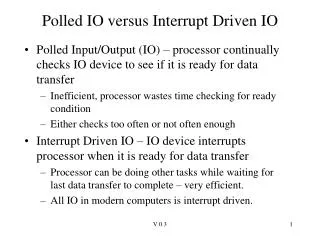
Polled IO versus Interrupt Driven IO. Polled Input/Output (IO) – processor continually checks IO device to see if it is ready for data transfer Inefficient, processor wastes time checking for ready condition Either checks too often or not often enough

E N D
Polled IO versus Interrupt Driven IO • Polled Input/Output (IO) – processor continually checks IO device to see if it is ready for data transfer • Inefficient, processor wastes time checking for ready condition • Either checks too often or not often enough • Interrupt Driven IO – IO device interrupts processor when it is ready for data transfer • Processor can be doing other tasks while waiting for last data transfer to complete – very efficient. • All IO in modern computers is interrupt driven. V 0.3
Polled IO: getch() This is polled IO. Note that the processor is continually polling to see if data is available. /* return 8 bit char from Receive port */unsigned char getch (){ unsigned char c; /* wait until character is received */ while (!RCIF); c = RCREG; return(c);} Time spent checking for data availability is WASTED time. In some applications this time can be spent doing something else. V 0.3
Interrupt-driven IO In this example, the arrival of a character to RCREG triggers an interrupt - the normal program execution is halted, interrupt service routine executed which reads the character, saves in a temporary location. Program Execution Interrupt service main(){ instrA instrB ….. instrN instrN+1 instrN+2 interrupt service subroutine…. read character from serial port, store in temporary location, set flag return from interrupt Character input to RCREG triggers interrupt V 0.3
PIC18 Interrupts (Chap 8 of datasheet) • Many PIC18 interrupt sources • When character is received on serial port • When character is finished transmitting on serial port • When A/D conversion is finished • When external pin RB0 is pulled low • Many more • Interrupt Enable, Flag bits • Each interrupt source has an ENABLE bit that allows an interrupt to be generated if interrupt condition is met. By default, interrupts are NOT enabled. • Each interrupt source also has a FLAG bit that indicates if the interrupt has occurred. • Each interrupt source also has a PRIORITY bit that allows it to be assigned a low or high priority. V 0.3
Interrupt Logic TMR0IF : flag bit, ‘1’ indicates event is true. High Priority Interrupt TMR0IE : enable bit, must be ‘1’ for interrupt to be generated. TMR0IP : priority bit, ‘1’ high priority, ‘0’ low priority. Low Priority Interrupt V 0.3
Interrupt Priorities • When an interrupt occurs, processor finishes current instruction, and calls an Interrupt Service Routine (ISR) • High priority interrupt routine at location 0x0008 • Low priority interrupt routine at location 0x0018 • An interrupt service routine should determine source of interrupt, and service it (i.e, do the interrupt function). • A high priority interrupt can interrupt the ISR of a low priority interrupt, but not vice versa • A high priority interrupt cannot interrupt (should not) interrupt itself. V 0.3
Interrupt Priorities (cont) • Interrupt priorities can be disabled by setting the IPEN bit (RCON[7]) to ‘0’. • All priorities are classified as high priority (interrupt jumps to 0x0008). • This is the mode that will be used for lab and class • This is compatible with PIC16 micros • We have no need for priorities in our lab exercises. V 0.3
GIE, PEIE • Global interrupt enable (GIE, INTCON[7]) can be used to disable all interrupts • By default, all interrupts disabled • Peripheral interrupt enable (PEIE, INTCON[6]) can be used to disable all peripheral interrupts • By default, all peripheral interrupts disabled • Peripheral interrupts are those associated with peripheral subsystems such as the USART, the Analog/Digital converter, timers, etc. • If priorities are enabled, • the GIE bit is known as GIEH (GIE for high priority interrupts) • PEIE bit is known as GIEL (GIE for low priority interrupts). V 0.3
When an enabled interrupt occurs... • GIE bit is CLEARED – this disables further interrupts (do not want to get caught in an infinite loop!) • If priorities are enabled, either GIEH or GIEL is cleared, depending on interrupt priority • Return address is pushed on the stack • W, STATUS, BSR saved in shadow registers • Jump to 0x0008 (high priority) or 0x0018 low priority interrupt is done V 0.3
PIC18 Interrupt V 0.3
ISR Responsibilities • Must save the processor context (W register, and Status Register, and BSR if necessary) • If not saved, normal program execution will become unpredictable since interrupt can happen at anytime • If ISR uses registers such as FSRx or PRODH/PRODL, must save these also!!!!! • Must determine the source of the interrupt • If multiple interrupts are enabled, check flag bit status • Must service the interrupt (clear interrupt flag) • E.g., for received character interrupt, read the RCREG, this clears the RCIF bit automatically. • Restore processor context • Execute RETFIE (return from interrupt) • Sets GIE to enable interrupts, reads PC from stack V 0.3
Shadow Registers • An interrupt can occur at any point in the execution of program. • The ISR will, at a minimum, change W and STATUS, and probably the BSR • These must be saved on ISR entry, and restored on ISR exit • Shadow registers were added with the PIC18 • W, STATUS, and BSR are registers are saved automatically on interrupt • Will be restored on exit by the RETFIE (return from interrupt) if the ‘s’ bit is set in the instruction word - the PICC18 C compiler uses ‘RETFIE 1’ which restores the W, STATUS, BSR on return. • Shadow registers can only be used with high priority interrupts • If low priority interrupt uses shadow registers, then can be overwritten by high priority interrupt V 0.3
cblock 0x7D w_temp, status_temp, bsr_temp endc org 0x008 goto isr_high_priority org 0x0018 goto isr_low_priority org 0x????isr_high_priority ;;; ISR high priority code retfie 1 ;; use shadow regisr_low_priority movwf w_temp ; context movff STATUS,status_temp movff BSR, bsr_temp ;;....ISR CODE ... ;;.... . . . movff bsr_temp,bsr ; restore context movf w_temp,w movff status_temp,STATUS retfie ISR Assembly space for w, status, bsr high priority ISR can use shadow registers (fast stack) low priority must explicity save the processor context restore context, do not use shadow registers on ‘retfie’ V 0.3
PIC18 ISR in C ‘interrupt’ keyword indicates this is ISR, high priority by default. unsigned char received_char;unsigned char got_char_flag; /* interrupt service routine */void interrupt pic_isr(void){ /* see if this interrupt was generated by a receive character */ if (RCIF) { /* check RCIF bit *//* reading this register clears interrupt bit */ received_char = RCREG; got_char_flag = 1; } } Check if receive char generated interrupt Read character, set semaphore for main() function Do not have to clear RCIF as it is cleared automatically by reading RCREG. V 0.3
Enabling Interrupts in C // code for serial port setup not shown // enable interrupts IPEN = 0; // disable priorities IPEN = RCON(7) RCIE = 1; // enable receive int, RCIE = PIE1(5) PEIE = 1; // enable peripheral intr, PEIE = INTCON(6) GIE = 1; // enable global intr, GIE = INTCON(7) for(;;) { // wait for interrupt while (!got_char_flag); c = received_char; got_char_flag =0; // clear flag c++; // increment Char putch (c); // send the char } Set by interrupt service routine – this is a semaphore. Get character read by interrupt service routine V 0.3
What is a semaphore? The main() code (i.e. foreground code) must be signaled when an interrupt action has occurred. The isr() code (i.e, background code) must perform the IO action that is caused by the interrupt. After servicing the IO, it must signal the main() code via some variable to indicate that the interrupt occurred. A variable used by an ISR to signal to main() code that an interrupt has occurred is called a semaphore. V 0.3
Soooooo…when are interrupts useful? Previous example simply illustrated the use of interrupts for reading serial data. Interrupt usage was not really needed since main routine just waited for data to arrive so no advantage over polled IO. Interrupts for serial IO useful when cannot poll serial port often enough! Get serial data Do calculation New serial data arrives, if not using ISR to save data in buffer, will miss it!! Output result V 0.3
doroot.c Read decimal number in ASCII format from serial port Calculate integer square root New data can arrive. Current ISR only has room to save ONE character. Depending on baud rate, can have overrun error (input FIFO fills up before we read data again). Output result to serial port V 0.3
Buffering Data for Interrupt IO • A circular buffer is most often used to handle interrupt driven INPUT. • A circular buffer requires the following pointers • base address of memory buffer • head index (head pointer) • tail index (tail pointer) • size of buffer • A circular buffer is simply another name for a FIFO (First-In-First-Out) buffer. • The name circular buffer helps to visualize the wraparound conditon V 0.3
Circular buffer, 8 locations long When buffer is empty, head = tail index ??? tail head ???? ???? ???? ???? ???? ???? ???? V 0.3
Circular buffer, write operation Interrupt service routine places items in memory buffer by incrementing head index, then storing value write a value write a 2nd value ??? tail ??? tail head dataA dataA ???? head dataB ???? ???? ???? ???? ???? ???? ???? ???? ???? ???? V 0.3
Circular buffer, read operation Input function occassionally checks to see if head not equal to tail, if true, then read value by incrementing tail, then reading memory. read dataA value read dataB value ??? ??? dataA tail dataA head dataB tail head dataB ???? ???? ???? ???? ???? ???? ???? ???? ???? ???? V 0.3
Circular buffer, wraparound when head pointer gets to end of buffer, set back to top of buffer (wraparound) head at end of buffer head at end of buffer ??? head dataH dataA dataA dataB tail dataB tail dataC dataC dataD dataD dataE dataE dataF dataF head dataG dataG V 0.3
Circular buffer, buffer FULL buffer FULL occurs if interrupt service routines increments head pointer to place new data, and head = tail!!!! near overflow buffer FULL dataH dataH head dataI dataI dataB tail head dataJ tail dataC dataC Function taking data out of buffer thinks buffer is empty!!!! dataD dataD dataE dataE dataF dataF dataG dataG V 0.3
How to pick size of circular buffer? • Must be big enough so that buffer full condition never occurs • Routine that is taking data out of buffer must check it often enough to ensure that buffer full condition does not occur. • If buffer fills up because not checking often enough, then increase the size of the buffer • No matter how large buffer is, must periodically read the data. • Buffer must be big enough so that bursts of data into buffer does not cause buffer full condition. V 0.3
ISR for Interrupt Driven Serial IO triggered when serial data arrives. Save in buffer. #define BUFSIZE 2unsigned char ibuf[BUFSIZE];unsigned char head,tail; void interrupt pic_isr(void){ /* see if this interrupt was generated by a receive character */ if (RCIF) { /* check RCIF bit */ head = head + 1; if (head == BUFMAX) head = 0; // reading this register clears interrupt bit ibuf[head] = RCREG; }} Increasing buffer size will increase amount of time that main{} code can wait before reading input buff. V 0.3
New getch() for Interrupt Receive Wait for ISR to trigger and save data in buffer. Combination of head/tail is the semaphore!!! unsigned char getch (void){ unsigned char c; while (head == tail) { asm("clrwdt"); }; tail = tail + 1; if (tail == BUFMAX) tail = 0; c = ibuf[tail]; return(c);} Must wrap tail pointer if at end of buffer. Read data from buffer V 0.3
Interrupt Driven LED/Switch IO Implement this using an interrupt-driven FSM approach V 0.3
configured for falling edge interrupt led_blink, led_on are semaphores to main() code ISR does not have any software delay loops! Do NOT want wasted time in ISR! It should just handle the IO. V 0.3
Semaphores led_blink, led_on control LED state in main() loop. V 0.3
What do you have to know? • How interrupts behave on the PIC18 for serial IO • Function of PEIE, GIE bits • Responsibilities of ISR • Assembly language structure of ISR in PIC18 • ISR in PICC C • Circular buffer operation • Interrupt-driven LED/Switch IO V 0.3