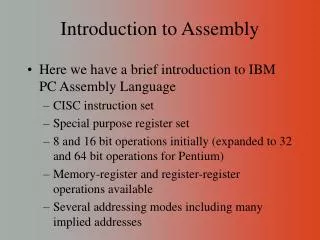
ARM's CPU Architecture and Programming
350 likes | 462 Views
Learn about ARM's CPU architecture including registers, ALU, and simple programming examples. Explore data and program memory access, RISC architecture, and instructions for arithmetic calculations. Discover how to write programs for ARM CPUs and utilize memory functions.

ARM's CPU Architecture and Programming
E N D
Presentation Transcript
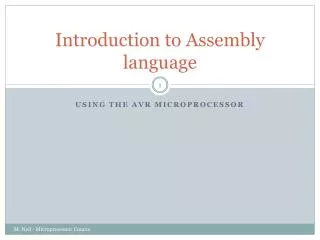
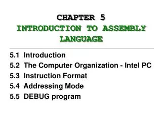
Introduction to AssemblyChapter 2 Sepehr Naimi www.NicerLand.com
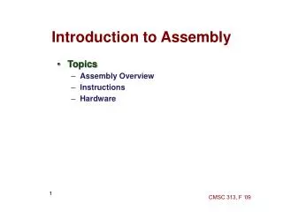
Topics • ARM’s CPU • Its architecture • Some simple programs • Data Memory access • Program memory • RISC architecture
ARM ’s CPU R0 R1 R2 … R13 (SP) R14 (LR) F C T N V I M4-M0 Z • ARM ’s CPU • ALU • Registers • General Purpose registers (R0 to R12) • PC register (R15) • Instruction decoder CPU ALU CPSR: R15 (PC) registers Instruction decoder Instruction Register
CPU 4
Some simple instructions1. MOV (MOVE) • MOV Rd, Rs • Rd = Rs • Example: • MOV R5,R2 • R5 = R2 • MOV R9,R7 • R9 = R7 • MOV Rd, #k • Rd = k • k is an 8-bit value • Example: • MOV R5,#53 • R5 = 53 • MOV R9,#0x27 • R9 = 0x27 • MOV R3,#0b11101100
LDR pseudo-instruction (loading 32-bit values) • LDR Rd, =k • Rd = k • k is an 32-bit value • Example: • LDR R5,=5543 • R5 = 5543 • LDR R9,=0x123456 • R9 = 0x123456 • LDR R4,=0b10110110011011001
Some simple instructions2. Arithmetic calculation • Opcode destination, source1, source2 • Opcodes: ADD, SUB, AND, etc. • Examples: • ADD R5,R2,R1 • R5 = R2 + R1 • SUB R5, R9,#23 • R5 = R9 - 23
A simple program • Write a program that calculates 19 + 95 MOV R6, #19 ;R6 = 19 MOV R2, #95 ;R2 = 95 ADD R6, R6, R2 ;R6 = R6 + R2
A simple program • Write a program that calculates 19 + 95 - 5 MOV R1, #19 ;R6 = 19 MOV R2, #95 ;R2 = 95 MOV R3, #5 ;R21 = 5 ADD R6, R1, R2 ;R6 = R1 + R2 SUB R6, R6, R3 ;R6 = R6 - R3 MOV R1, #19 ;R6 = 19 MOV R2, #95 ;R2 = 95 ADD R6, R1, R2 ;R6 = R1 + R2 MOV R2, #5 ;R21 = 5 SUB R6, R6, R2 ;R6 = R6 - R2
Memory Map in Raspberry Pi Example: Write a program that copies the contents of location 0x80 of into location 0x88. LDR (Load register) LDR Rd, [Rx] ;Rd = [Rx] Example: LDR R4,=0x20000000 LDR R1, [R4] STR (Store register) STR Rx,[Rd] ;[Rd]=Rx Example: Add contents of location 0x90 to contents of location 0x94 and store the result in location 0x300. Example: ;[0x20000000]=0x12345678 LDR R5,=0x12345678 LDR R2, =0x20000000 STR R5,[R2] ; [R2] = R5 Solution: LDR R6,=0x90 ;R6 = 0x90 LDR R1,[R6] ;R1 = [0x90] LDR R6,=0x94 ;R6 = 0x94 LDR R2,[R6] ;R1 = [0x94] ADD R2,R2,R1 ;R2 = R2 + R1 LDR R6,=0x300 ;R6 = 0x300 STR R2,[R6] ;[0x300] = R2 Solution: LDR R2,=0x80 ;R2 = 0x80 LDR R1,[R2] ;R1 = [0x80] LDR R2,=0x88 ;R2 = 0x88 STR R1,[R2] ;[0x88] = R1
LDRB, LDRH, STRB, STRH LDR Rd,[Rs] STR Rs,[Rd] LDRB Rd,[Rs] LDRH Rd,[Rs] STRB Rs,[Rd] STRH Rs,[Rd]
Status Register (CPSR) Solution: 52 0101 0010 - 73 0111 0011 DF 1101 1111 R0 = 0xDF Z = 0 because the R20 has a value other than zero after the subtraction. C = 0 because R1 is bigger than R0 and there is a borrow from D32 bit. Solution: 9C 1001 1100 - 9C 1001 1100 00 0000 0000 R0 = $00 Z = 1 because the R20 is zero after the subtraction. C = 1 because R21 is not bigger than R20 and there is no borrow from D32 bit. Solution: 38 00000000 00000000 00000000 0011 1000 + 2F 00000000 00000000 00000000 0010 1111 67 00000000 00000000 00000000 01100111 R6 = 0x67 C = 0 because there is no carry beyond the D31 bit. Z = 0 because the R6 (the result) has a value other than 0 after the addition. Solution: 0xA5 1010 0101 - 0x23 0010 0011 0x82 1000 0010 R0 = 0x82 Z = 0 because the R20 has a value other than 0 after the subtraction. C = 1 because R1 is not bigger than R0 and there is no borrow from D32 bit. Solution: 0000009C 00000000 00000000 00000000 10011100 + FFFFFF64 11111111 11111111 11111111 01100100 100000000 1 00000000 00000000 00000000 00000000 R0 = 00000000 C = 1 because there is a carry beyond the D7 bit. Z = 1 because R0 (the result) has a value 0 in it after the addition. Example: Show the status of the C and Z flags after the addition of 0x38 and 0x2F in the following instructions: MOV R6, #0x38 ;R6 = 0x38 MOV R7, #0x2F ;R17 = 0x2F ADDS R6, R6,R7 ;add R7 to R6 Example: Show the status of the Z flag after the subtraction of 0x73 from 0x52 in the following instructions: LDR R0,=0x52 LDR R1,=0x73 SUBS R0,R0,R1 ;subtract R1 from R0 Example: Show the status of the Z flag after the subtraction of 0x9C from 0x9C in the following instructions: LDR R0,=0x9C LDR R1,=0x9C SUBS R0,R0,R1 ;subtract R21 from R20 Example: Show the status of the C and Z flags after the addition of 0x0000009C and 0xFFFFFF64 in the following instructions: LDR R0,=0x9C LDR R1,=0xFFFFFF64 ADDS R0,R0,R1 ;add R1 to R0 Example: Show the status of the Z flag after the subtraction of 0x23 from 0xA5 in the following instructions: LDR R0,=0xA5 LDR R1,=0x23 SUBS R0,R0,R1 ;subtract R1 from R0 CPSR: Negative Thumb Interrupt oVerflow Zero carry
Instructions, pseudo-instructions, and assembler directives • Instructions: they are the real instructions of the CPU • mov r5,#23 • add r4,r5,r6 • Pseudo-instructions: the pseudo-instructions are translated to some real instructions by the assembler • ldr r5,=0x253234 • Assembler directives: • .equ myValue, 0x3fffc045 • .global _start
.global and .extern directives file1.s file2.s .text .extern myFunc ... bl myFunc ... .text .global myFunc myFunc: add r2,r1,r5 ... ...
Assembler Directives .EQU • .equ name,value • Example: .equ COUNT, 0x25 mov r1, #COUNT ;r1 = 0x25 mov r2, #COUNT + 3 ;r2 = 0x28
Assembler Directives.INCLUDE hFile.inc .equ SREG = 0x3f .equ SPL = 0x3d .equ SPH = 0x3e .... Program.asm .include “hFile.inc” • .INCLUDE “filename.ext”
A simple program @ ARM Assembly language program to add some data @ and store the SUM in r0. .text .global _start _start: @ the beginning point for ARM assembly programs mov r1, #0x25 @ r1 = 0x25 mov r2, #0x34 @ r2 = 0x34 add r0, r2, r1 @ r0 = r2 + r1 mov r7, #1 svc 0 @ system call to terminate the program
A Simple Code that Stores Fixed Data in Program Memory @ storing data in program memory. .text .global _start _start: ldr r2, =our_fixed_data @ point to our_fixed_data @ load r0 with the contents of memory pointed to by r2 ldrb r0, [r2] @ terminate the program mov r7, #1 svc 0 our_fixed_data: .byte 0x55, 0x33, 1, 2, 3, 4, 5, 6 .word 0x23222120, 0x30 .hword 0x4540, 0x50
Defining variables A, B, and C in RAM .text .global _start _start: @ r1 = a ldr r0, =a @ r0 = addr. of a ldr r1, [r0] @ r1 = value of a @ r2 = b ldr r0, =b @ r0 = addr. of b ldr r2, [r0] @ r2 = value of b @ c = r1 + r2 (c = a + b) add r3, r1, r2 @ r3 = a + b ldr r0, =c @ r0 = addr. of c str r3, [r0] @ c = r3 mov r7, #1 @ terminate the program svc 0 @ allocates the followings in data memory .data a: .word 5 b: .word 4 c: .word 0
Flash memory and PC register start E3A01025 +04 E3A02034 +08 E0810002 +12 E3A07001 +16 EF000000 .text .global _start _start: mov r1, #0x25 mov r2, #0x34 add r0, r2, r1 mov r7, #1 svc 0 E3A01025 32-bit E3A02034 E0810002 E3A07001 EF000000 10 14 4 C 0 8 6
How to speed up the CPU • Increase the clock frequency • More frequency More power consumption & more heat • Limitations • Change the architecture • Pipelining • RISC
Changing the architectureRISC vs. CISC • CISC (Complex Instruction Set Computer) • Put as many instruction as you can into the CPU • RISC (Reduced Instruction Set Computer) • Reduce the number of instructions, and use your facilities in a more proper way.
RISC architecture • Feature 1 • RISC processors have a fixed instruction size. It makes the task of instruction decoder easier. • In ARM the instructions are 4 bytes. • In Thumb2 the instructions are either 2 or 4 bytes. • In CISC processors instructions have different lengths • E.g. in 8051 • CLR C ; a 1-byte instruction • ADD A, #20H ; a 2-byte instruction • LJMP HERE ; a 3-byte instruction
RISC architecture • Feature 2: reduce the number of instructions • Pros: Reduces the number of used transistors • Cons: • Can make the assembly programming more difficult • Can lead to using more memory
RISC architecture • Feature 3: limit the addressing mode • Advantage • hardwiring • Disadvantage • Can make the assembly programming more difficult
RISC architecture • Feature 4: Load/Store LDR R8,=0x20 LDR R0,[R8] LDR R8,=0x220 LDR R1,[R8] ADD R0, R0,R1 LDR R8,=0x230 STR R0,[R8]
RISC architecture LDR R2, [R4] ; R2 = [R4] ADD R0,R0,R1 ; R20 = R20 + R21 SUB R3,R3,R4 Fetch Decode Execute SUB R3,R3,R4 ADD R0, R0,R1 LDR R2, [R4] • Feature 5 (Harvard architecture): separate buses for opcodes and operands • Advantage: opcodes and operands can go in and out of the CPU together. • Disadvantage: leads to more cost in general purpose computers. CPU Control bus Control bus Code Memory Data Memory Data bus Data bus Address bus Address bus
RISC architecture • Feature 6: more than 95% of instructions are executed in 1 machine cycle
RISC architecture • Feature 7 • RISC processors have at least 32 registers. Decreases the need for stack and memory usages. • In ARM there are 16 general purpose registers (R0 to R15)