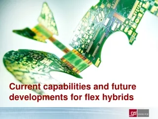
Current capabilities and future developments for flex hybrids
Current capabilities and future developments for flex hybrids. Author. Dr. Frank Bose CEO GS Swiss PCB since 2002 Low Energy Plasma Physics RF engineering Semiconductor Manufacturing Equipment Manufacturing PCB Manufacturing frank.bose@swisspcb.ch +41 41 854 4800. Table of Contents.

Current capabilities and future developments for flex hybrids
E N D
Presentation Transcript
Current capabilities and future developments for flex hybrids
Author Dr. Frank Bose CEO GS Swiss PCB since 2002 • Low Energy Plasma Physics • RF engineering • Semiconductor Manufacturing • Equipment Manufacturing • PCB Manufacturing frank.bose@swisspcb.ch +41 41 854 4800
Table of Contents • Technology Drivers • Speed, High Frequency • Controlled Impedance • Materials, LCP • Density, Miniaturization • Pitch, Defect Density • Vias, Annular Ring • Thin dielectric materials • Reliability • Rigid-Flex • Plating • Metrology • (GS Roadmap • Other Developments • HicoFlex • Embedded Components (actives, passives and wave guides)
Clock Speed and RF Frequency • Ensure geometrical reproducibility of art work • Extract S-Parameters for better models and to account for parasitics • Find flex materials with good radio frequency properties • Material must posses good properties with respect to PCB manufacturing
Micro Strip Line Influence of geometrical variation on impedance
S-Parameter extraction required • Supplier value for er in FR4 is around 4.2-4.5 fitted values are closer to 3.7 ??? • Polar is de facto industry standard SW & measurement • Polar calculates around 1 MHz • Polar measurements done in time domain • S-Parameter extraction required for better models • Broader frequency range and parasitics • Skin effect & radiation due to treatment taken into account
Better flex materials required, i.e., LCP • Better mechanical stability • Low moisture absorption (stability, vacuum) • Better RF characteristics Tentzeris et al., IEEE Transactions on Microwave Theory and Techniques, Vol. 52, No.4, 2004
Example of LCP Substrates • LCP currently broadly used as high speed flex layer in hybrid build ups (LCP combined with other materials) • Full LCP build not readily available because of lamination problems, pattern dependence • Supply:Rogers, Nippon Steel (Espanex), and now Dupont
Density / Miniaturization • Main problem is isotropic nature of wet chemistry etching • Subtractive process vs additive process (panel plating vs pattern plating) • Stacked vias are reducing amount of real estate required for interconnects • Annular rings are required because of drill scatter even with CCD camera positioning • Defect density (defects per m2) is limiting availability of fine pitch PCBs
Subtractive Process • Easy process flow, economical • Pitch (p) limited top > 3*T T = Cu + resist thickness resist copper wanted reality laminate
Additive Process • Advanced process flow • Pattern dependence resist Seed copper plating etch laminate
Vias, Annular Ring and Catch Pad • Pads must be considerably larger than via diameter • Blind via must have aspect ratio > 1:1 • Stacked via enables real estate saving, no break-outs
What is limiting fine pitch processes? • Availability of thin seed layer materials (Hofstetter AG) • Defect density is not yet well controlled Currently 100mm pitch is available for small PCBs (3x3 cm)
Reliability & Metrology Stacked Vias expected to exhibit higher reliability • Base line and test in progress • Already used in implantable devices Metallization Problems • Plating is well understood • Choose a reliable vendor Full Flex and Rigid-flex • High reliability applications (aerospace) • Hearing Instrument hybrids as full – flex modules • Reduce interconnection complexity and connector failures
E-Test Polishing of Micro Section Micro Section Final Inspection 3D Image FAIR
Some other Developments • HiCoFlex (SHIFT, Hightec MC) • Embedded Components (VISA, HERMES, embedded chip (Würth, AT&S, Imbera, etc.) embedded interposer (Schweizer etc.) embedded passives • Embedded fibre-optics (Varioprint, PPC Cham) • Inkjet printed PCBs (cheap, but low performance)
HiCoFlex: Thin spin-on polyimide H. Burkhard, Hightec MC, Lenzburg, 6./7. September 2007
HiCoFlex • Spin-on polyimide film guaranties thin layer • Very fine etching possible due to sputtered seed layers • One sided assembly only • Panel size to increase from 6x6 inch to 12x24 • Single Source !
Embedded Die • Thermo-sonic flip chip embedded in PCB substrate • Laser cavity enables placement of thinned die R. Schönholz, Würth Schopfheim, Plus 2/2009, Leuze Verlag
Embedded Interposer • Lamination of interposer board into Multilayer • Testability, Known Good Interposer T. Gottwald et al., Schweizer Electronic AG, Plus 2/2009, Leuze Verlag
Embedded Passives • Resistive and capacitive layers within multilayer • Embedded ceramic components W.J. Borland et al., Dupont iTechnologies
Folded-in instead of embedded ! GS Swiss PCB / Phonak • Two layer flex PCB for flip chip (COF) • SiP for medical application • Polyimide thickness: 25 µm • Better testability of MCM • Better form factor as dielectric is thinner than standard pre-pregs • Easier supply chain integration • PCB yield does not push up electronics cost
Embedded Optical Waveguides Varioprint / IntexyS Photonics • Embedded polymer wave guide • High End Server backplane solution http://www.zurich.ibm.com/news/06/photonics_d.html
Summary • PCB technology is faced with the challenge of reducing the widening gap of silicon pitch and board pitch • Ever higher clock rates require precise artwork etching, often beyond current IPC Class 3 requirements • Reduction of foot print will evolve gradually, no revolutionary technology in sight • Material technology to evolve to include better RF properties, thinner dielectrics and thinner copper cladding • Increase in electrical function density to be expected with the use of embedded components, either active or passive, however, the jury is still out!