ECE 368 --- CAD-Based Logic Design
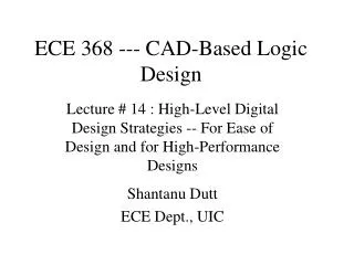
ECE 368 --- CAD-Based Logic Design. Lecture # 14 : High-Level Digital Design Strategies -- For Ease of Design and for High-Performance Designs Shantanu Dutt ECE Dept., UIC. Main Problem. Subprob. Subprob. Subsub prob. Subsub prob. Subsub prob. Subsub prob.

ECE 368 --- CAD-Based Logic Design
E N D
Presentation Transcript
ECE 368 --- CAD-Based Logic Design Lecture # 14 : High-Level Digital Design Strategies -- For Ease of Design and for High-Performance Designs Shantanu Dutt ECE Dept., UIC
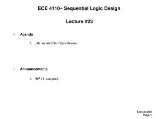
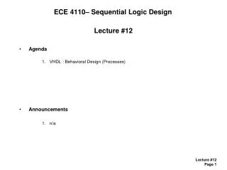
Main Problem Subprob. Subprob. Subsub prob. Subsub prob Subsub prob. Subsub prob. Strategy 1: Divide and Conquer (D&C) • Think of the design problem as a computation • Divide the main problem into 2 or more subproblems which when solved will lead to the solution to the main problem • Some “stitching up” of subprob solns may be required • Do this recursively, until each small problem can be solved in an obvious way, e.g. using truth tables (TTs)
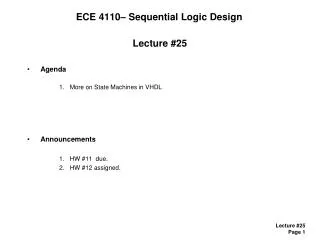
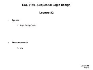
Add n-bit #s X, Y Add MS n/2 bits of X,Y Add LS n/2 bits of X,Y FA FA FA FA (a) D&C for Ripple-Carry Adder Add n-bit #s X, Y Add last n/4 bits Add last n/4 bits Add last n/4 bits Add last n/4 bits 4-bit CLA 4-bit CLA 4-bit CLA 4-bit CLA (b) D&C for Carry-Lookahead Adder Strategy 1: D&C (contd.) • Example: Ripple-Carry Adder (RCA) • Stitching up: Carry from LS n/2 bits is input to carry-in of MS n/2 bits at each level of the D&C tree. • Leaf subproblem: Full Adder (FA) • Example: Carry-Lookahead Adder (CLA) • Division: 4 subproblems per level • Stitching up: A more complex stitching up process (generation of “super” P,G’s to connect up the subproblems) • Leaf subproblem: 4-bit basic CLA with small p, g bits. • More intricate techniques (like P,G generation in CLA) for complex stitching up for fast designs may need to be devised that is not directly suggested by D&C. But D&C is a good starting point.
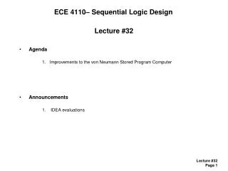
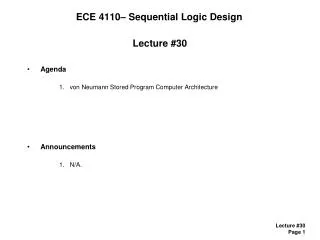
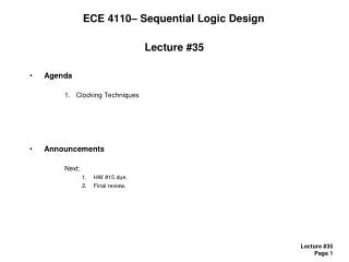
z & & & & Inputs z & & & & & & & Inputs Strategy 2: Fast Tree Designs for Associative Operations • An associative operation op is defined as one for which: A op B op C = (A op B) op C = A op (B op C) Thus, A op B op C op D = (A op B) op (C op D). • This means that (A op B) and (C op D) can be done simultaneously to speed up the operation and the results op’ed to get the final result. • Thus associative operations can be performed using tree-like designs to get the result in Theta(log n) time • At each level of the tree the op operations are performed simultaneously and their results are op’ed at the next higher level, and so forth • E.g. of assoc. oper: +, *, and, or, xor • E.g. of non-assoc. oper: -, / • E.g. designs: AND-tree, Wallace-tree multiplier (a) “Linear” AND’ing of n bits. Time = (n-1)d, d= & gate delay (b) Tree-based AND’ing of n bits. Time = d log(n).
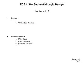
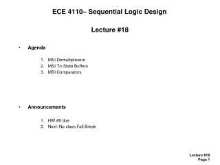
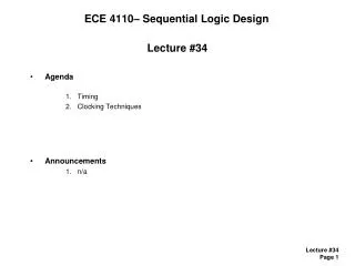
A x y A x y B(0,0) 0 0 4:1 Mux z B(0,1) 0 B(1,0) 1 1 0 B(1,1) 1 1 Strategy3: Speculative Computations --- Faster Designs B z (a) Original design: Time = T(A)+T(B) • If there is a data dependency between two or more portions of a computation (which may be obtained using D&C), don’t wait for the the “previous” computation to finish before starting the next one • Assume all possible input values for the next computation/stage B (e.g., if it has 2 inputs from the prev. stage there will be 4 possible input value combinations) and perform it using a copy of the design for possible input value. • All the different o/p’s of the diff. Copies of B are Mux’ed using prev. stage A’s o/p • E.g. design: Carry-Select Adder (at each stage performs two additions one for carry-in of 0 and another for carry-in of 1 from the previous stage) (b) Speculative computation: Time = max(T(A),T(B)) + T(Mux). Works well when T(A) approx = T(B) and T(A) >> T(Mux)
Registers inputs inputs start Unary Division Ckt (good ave case, bad worst case) Non- Restoring Div. Ckt (bad ave case, good worst case) Ext. FSM done1 done2 output output Mux select Register Strategy4: Get the Best of Both Worlds (Average and Worst Case Delays)! • Use 2 circuits with different worst-case and average-case behaviors • Use the first available output • Get the best of both (ave-case, worst-case) worlds • In the above schematic, we get the good ave case performance of unary division (assuming uniformly distributed inputs w/o the disadvantage of its bad worst-case performance)
Original ckt or datapath Stage 1 Stage 2 Conversion to a simple level-partitioned pipeline (level partition may not always be possible but other pipe- lineable partitions may be) Stage k Strategy5: Pipeline It!