Download
1 / 8
80 likes | 264 Views
Development of Two-Klystron M odulator T opologies for the CLIC Drive Beam / ETH Modulator. by Sebastian Blume ETH Zürich. Topology. Topology. Charging System. Features AC/DC stage available on market Parallel redundancy Constant power consumption Challenges:

E N D
Development of Two-Klystron Modulator Topologies for the CLIC Drive Beam / ETH Modulator by Sebastian Blume ETH Zürich
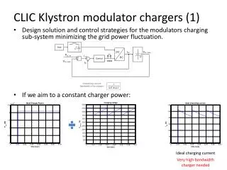
Charging System • Features • AC/DC stage available on market • Parallel redundancy • Constant power consumption • Challenges: • Ultra precise charging voltage Interleaving, precise voltage measurement • High efficiency Optimization procedure • High grid power quality Constant power, unity power factor
BouncerTopology • Interleaved buck-boost converter with short circuit switch • Features: • Output switching frequency up to 2.4 MHz • High repeatability • Parallel redundancy • Challenges: • High switching frequency 24-fold interleaving • High pulsed currents Parallelization of switches
Split Core Transformer with Cone Winding • Split core transformer (Matrix transformer) with cone winding • Secondary winding encloses all cores • Advantages: Higher dynamics (rise time) • Challenges • Long pulse length • Fast rise time • High efficiency Global optimization procedure
Optimization Procedure for Matrix Transformer Analytical approximations Core loss measurements FEM verification Optimization Procedure • 8 optim variables • Loss components included • Core loss measurements integrated • Analytical approximations for parasitics with FEM verification • Pulse shape analyzed in time domain Optimal design
Project Status • η • Rise time • Grid distortion • Repeatability Status • Overall topology selected • Transformer optimization procedure & design models ready • Bouncer optimization procedure & design models ready • Design models under experimental validation Challenges Timeline