Download
1 / 14
140 likes | 265 Views
This presentation by John Jones from Princeton University discusses the development of a generic trigger system for high-energy physics experiments, focusing on effective operation within a 6μs latency. It addresses the current challenges of the CMS trigger, including issues related to electrical noise, hardware complexity, and physics reach. The proposed solutions emphasize a more universal approach to trigger functionality by merging lower and higher-level processing, optimizing detector combinations, and improving overall performance while minimizing costs and complexity.

E N D
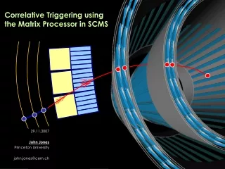
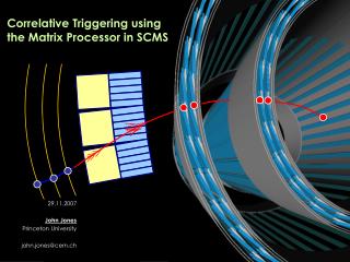
Correlative Triggering usingthe Matrix Processor in SCMS 29.11.2007 John Jones Princeton University john.jones@cern.ch
What Are We Trying To Do? We’re trying to build a generic trigger that can: Operate within a ~6μs trigger latency Provide access to as many physics channels as possible Be flexible to changes for physics we don’t know exisits… Avoid ‘issues’ of current trigger architecture – see next slides Uses as few unique hardware/technology modules as possible Complexity/cost/failure rate Presume here that we have a tracking trigger based on stacks: Outline will include basic pT measurement using double stacks But approach outlined is applicable to any combination of detectors John Jones (john.jones@cern.ch)
Issues with Current CMS Trigger – Electrical I’m going to discuss this from my personal experience… Environmental noise coupling from e.g. fluorescent lights Can be mitigated using LVDS provided VCM shift is less than 2V Can be further mitigated using a shielded cable, but this acts as a current dump Systems at either end must have very good (stable) grounding Not a typical CMS scenario Almost impossible to achieve with a O(100)kW trigger due to current loops CMS is not yet fully commissioned Copper links may yet cause problems…unpredictable WE STILL DON’T KNOW WHETHER THIS WILL BE STABLE USE OPTICAL LINKS FOR ALL INTER-CRATE CABLING John Jones (john.jones@cern.ch)
Issues with Current CMS Trigger - Cost Using a high-grade electrical cable is NOT necessarily cheaper: Optical fibre (multimode) is getting cheaper… …and avoids the performance issues of the cables Too many board types in CMS This is also one of the REAL latency issues: Every time we cross between two boards in CMS, we lose at least one clock Quick look through trigger chain – I found 10BX of connections that don’t need to exist Some boards really shouldn’t exist, e.g.: Tracker APVe (trigger logic) – could easily be split between tracker FED and GT GCTSource card (electro-optical conversion) – glue logic – loses 2BX Muon quiet bit system (serial-serial conversion) – glue logic – loses 3-5BX Even condensing simple algorithms into one FPGA saves latency John Jones (john.jones@cern.ch)
Issues with Current CMS Trigger – Physics Reach To go beyond current L1 trigger performance, look at HLT Significant improvements come from tracking The current ‘top 4 object’ approach isn’t necessarily appropriate Especially true for a tracking trigger Instead, consider a more generic approach Concentrate data into one system to allow objects to be combined Slightly different to current HLT No regional reconstruction – consider a full high-pT tracking trigger …but this choice is flexible… John Jones (john.jones@cern.ch)
Trigger Reconstruction Breakdown Break down into basic detector primitives: ECAL: Energy clusters with ET > <ET> + e.g. 3σnoise e(ET, η, φ) HCAL: Energy clusters with HT > <ET> + e.g. 3σnoise h(HT, η, φ) Tracker: Track with pT > cut t(pT, η, φ) Muon: Track with pT > cut μ(pT, η, φ) Break down into basic physics objects (not a complete list): Jet: Region (1.044x1.044) with (Σe + Σh) > t, central eMAX J(ET, η, φ) τ-jet: Jet, collimated τ(HT, η, φ) e: Region (0.087x0.087) with ET > t1, HT/ET < t2, correlated track e(pT, η, φ) γ: Region (0.087x0.087) with ET > t1, HT/ET < t2, central eMAX γ(ET, η, φ) ET MISS: Imbalance in net calorimeter energy sums ETMISS(ET, η, φ) Break down into compound (complex) physics primitives: H WW llνν: e > t1 && e > t2 && ETMISS > t2 H γγ: γ > t1 && γ > t2 Build topological triggering in from the beginning e.g. multi-jet with acoplanarity cut… John Jones (john.jones@cern.ch)
Proposal Merge the lower-level functionality of the RCT with the ECAL and HCAL TPGs Include zero-suppression from the start to reduce bandwidth e.g. ECAL LHC occupancy ~0.3%, SLHC ~3% Results in data having a packet structure… Merge the higher-level functionality of the GCT and GMT into a global pattern finder Project ALL of the primitives into an η, φ ‘trigger plane’ Produce basic physics objects, including tracking Standardise layout of trigger crates into η–slices containing all of φ This is better than the ‘mixed’ situation in CMS at the moment Simpler reconstruction for tracking, no difference for ECAL and HCAL Replace the GT with a topological processing architecture derived from primitives Produce basic physics objects, including tracking IMPORTANT: Zero-suppression implies iso-synchronous operation That means we go to a packet-based architecture with embedded BX information John Jones (john.jones@cern.ch)
Reconstruction Hierarchy TTPG ETPG HTPG μTPG ET HT pT pT GTPOG ηslices e,jet,μ… Iso-synchronous GT L1A Synchronised here Align trigger decision (with BX ID) with detector pipeline John Jones (john.jones@cern.ch)
Tracker/Muon TPG Presume local correlation is done using LUT on-detector Second-stage correlation is best done using z-correlation This lends itself to a ‘projective’ reconstruction technique Use first stage of processing as a ‘switch’ – forward data into internal plane Internal plane processor builds track (quadruplets) and projects onto CAL face Muons are similar, although more stations In any case, should also project to same CAL face as tracker r μ φ t t z η t John Jones (john.jones@cern.ch)
ECAL/HCAL TPGs e e e Slightly different problem – deposition is regional Clustering and pedestal issue Projection not required – already on a tower basis φ η John Jones (john.jones@cern.ch)
Global Trigger Physics Object Generator Combine ALL basic primitive objects at this point As an example, consider 0.087x0.087 towers (5x5 ECAL, 1x1 HCAL) Use combinatorial algorithm that maps directly into 2D layout of FPGAs Firmware is a ‘hybrid’ of different detector primitives No jets shown here – more complex but same basic principle ETPG: t+μ > threshold HTPG: e+t > threshold e+t > threshold e > threshold TTPG: φ μTPG: η John Jones (john.jones@cern.ch)
Synchronisation, Data Payload Structure and Flow Control Unify packet structure for TPGs Easy to manage, shared information at higher level Starts to look like telecom data (not surprising!) Interesting point – all modules will be able to ‘understand’ data wrapper Example structure: Flow control: There are more advanced methods, but presuming a fixed-link system: Flow control in iso-synchronous trigger can be managed ‘predictively’ System feeding data into next one ‘knows’ how full it is – can be managed Extreme fluctuations in data volume would be rejected… …but can be treated as a ‘forced’ trigger (i.e. something interesting happened) Synchronisation: Can be achieved by dynamically aligning packets upon reception in FPGA i.e. Rule is ‘Time of output – time of input <= allowed latency of module’ This is NOT truly asynchronous as we guarantee latency on a per-module basis • BX ID (8b – determined by L1 latency) • η • φ • Detector/physics primitive ID • Data payload (Could be compressed!) • ECC John Jones (john.jones@cern.ch)
Consequences GTPOG contains the physics primitive algorithms e.g. Jets, electrons, photons, muons, taus Has strong similarity with L2/L2.5 of HLT To operate efficiently, must be a shared project managed like HLT in CMSSW Open code, committed to a managed (e.g. Subversion) repository Groups without hardware development resources can contribute to firmware All common components should be merged, no ‘black box’ firmware (except COTS) e.g. Flow control logic, error checking/correction, etc… Mismatch between components due to ‘black box’ firmware has been a major problem for CMS Packet based structure is scalable Can be used to ‘wrap’ changes in physics algorithms e.g. new packet types for detector or physics primitives 2D map for GTPOG allows combinatorial paths to be merged for algorithms Regular, repeating structure – easy to generate in VHDL Lends itself to fast, compact implementations in FPGAs John Jones (john.jones@cern.ch)
Conclusions Have proposed an iso-synchronous topological trigger Zero-suppressed Packet based Scalable (Relatively) easy to adapt to new physics Less error-prone Shared firmware project for all components in GTPG and GT All of GTPG and GT uses same (Matrix) processor TTPG, ETPG, HTPG, etc.. would be similar, with some adaptation for specific FE Leverages current development work and reduces risk/cost/complexity Use the Matrix card for most of trigger system No TTC/QPLL in most of chain Ethernet for control system Flow control implicit to system FPGAs can operate at their maximum performance John Jones (john.jones@cern.ch)