ELEC 412 RF & Microwave Engineering
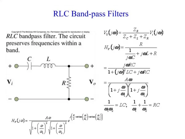
ELEC 412 RF & Microwave Engineering. Fall 2004 Lecture 13. Band-Pass Filter Design Example. Attenuation response of a third-order 3-dB ripple bandpass Chebyshev filter centered at 2.4 GHz. The lower cut-off frequency is f L = 2.16 GHz and the upper cut-off frequency is f U = 2.64 GHz.

ELEC 412 RF & Microwave Engineering
E N D
Presentation Transcript
ELEC 412 RF & Microwave Engineering Fall 2004 Lecture 13
Band-Pass Filter Design Example Attenuation response of a third-order 3-dB ripple bandpass Chebyshev filter centered at 2.4 GHz. The lower cut-off frequency is f L= 2.16 GHz and the upper cut-off frequency is f U = 2.64 GHz.
RF/W Stripline Filters • Filter components become impractical at frequencies higher than 500 MHz • Can apply the normalized low pass filter tables for lumped parameter filters to stripline filter design • Richards Transformation and Kuroda’s Identities are used to convert lumped parameter filter designs to distributed filters
Richards Transformation: Lumped to Distributed Circuit Design • Open- and short-circuit transmission line segments emulate inductive and capacitive behavior of discrete components • Based on: • Set Electrical Length l = /8 so
Richards Transformation: Lumped to Distributed Circuit Design • Richards Transform is: and • For l = /8, S = j1 for f = fo= fc
Richards Transformation: Lumped to Distributed Circuit Design
Unit Elements : UE • Separation of transmission line elements achieved by using Unit Elements (UEs) • UE electrical length: = /4 • UE Characteristic Impedance ZUE
Realizations of Distributed Filters • Kuroda’s Identities use redundant transmission line sections to achieve practical microwave filter implementations • Physically separates line stubs • Transforms series stubs to shunt stubs or vice versa • Change practical characteristic impedances into realizable ones
Filter Realization Procedure • Select normalized filter parameters to meet specifications • Replace L’s and C’s by o /8 transmission lines • Convert series stubs to shunt stubs using Kuroda’s Identities • Denormalize and select equivalent microstriplines
Filter Realization Example • 5th order 0.5 dB ripple Chebyshev LPF • g1 = g5 = 1.7058, g2 = g4 = 1.2296, g3 = 2.5408, g6 =1.0
Filter Realization Example • Y1 = Y5 = 1.7058, Z2 = Z4 = 1.2296, Y3 = 2.5408; and Z1 = Z5 = 1/1.7058, Z3 = 1/2.5408
Filter Realization Example • Utilizing Unit Elements to convert series stubs to shunt stubs
Filter Realization Example • Apply Kuroda’s Identities to eliminate first shunt stub to series stub
Filter Realization Example • Deploy second set of UE’s in preparation for converting all series stubs to shunt stubs
Filter Realization Example • Apply Kuroda’s Identities to eliminate all series stubs to shunt stubs • Z1 = 1/Y1 =NZ2 = (1+Z2/Z1)Z2 =1+(1/0.6304); Z2 = 1 and Z1 = 0.6304
Filter Realization Example • Final Implementation
Filter Realization Example • Frequency Response of the Low Pass Filter


![[f´‚nE˘RIks]](https://cdn0.slideserve.com/1072532/f-ne-riks-dt.jpg)


![[f´‚nE˘RIks]](https://cdn2.slideserve.com/5310017/f-ne-riks-dt.jpg)