Structured Design Concepts in VHDL
720 likes | 752 Views
Learn the fundamental concepts of structured design using VHDL language. Explore abstraction hierarchies, design representations, behavioral descriptions, and the design process step by step.

Structured Design Concepts in VHDL
E N D
Presentation Transcript
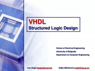
Structured Logic Design With VHDL Ivan Dugic idugic@verat.net Veljko Milutinovic vm@etf.bg.ac.yu School of Electrical Engineering University of Belgrade Department of Computer Engineering
Reference • James R. Armstrong, F. Gail Gray Structured Logic Design with VHDL, PTR Prentice Hall 1993. Ivan Dugic 2/72
Introduction • VHDL - VHSIC Hardware Description Language • VHSIC - Very High Speed Integrated Circuit • Development of a hardware description language model as a step in digital design at a high level of abstraction • Development of VHDL began in 1983,sponsored by Department of defense, further developed by the IEEE and released as IEEE Standard 1076 in 1987 • Today it is De facto industry standard for hardware description languages 3/72 Ivan Dugic
Structured Design Concepts Ivan Dugic
Structured Design ConceptsThe abstraction hierarchy • The abstraction hierarchy employed by digital designers is a set of interrelated system representation • Can be expressed in two domains: structural domain, behavioral domain • Structural domain – component model is described in terms of an interconnection of more primitive components • Behavioral domain – component model is described by defining its input/output response • VHDL is used for behavioral description 5/72 Ivan Dugic
Structured Design ConceptsThe abstraction hierarchy • Six abstraction hierarchy levels of detail commonly used in design: silicon, circuit, gate, register, chip and system 6/72 Ivan Dugic
Structured Design Concepts Representations • Design representations can be either pictorial or textual • Pictorial forms (used for structural description): block diagrams, timing diagrams, state tables etc. • Textual methods of representation (used for behavioral description): natural languages (e.g., English), equations (e.g.,Boolean) and computer languages (Hardware Description Language) • Pictures are better for illustrating interrelationships • Text is better for representing complex behavior • Excessive use of either pictures or text result in a loss of perspective – “one cannot see the forest for the trees.” 7/72 Ivan Dugic
Structured Design ConceptsTypes of behavioral descriptions • Two types of behavioral description – algorithmic and data flow • Algorithmic – a procedure or program defining the I/O response with no implies of any particular physical implementation • Data flow – a behavioral description in witch the data dependencies is the description match those in a real implementation • Algorithmic and data flow descriptions are HDL implementations of behavior at the chip and register levels respectively 8/72 Ivan Dugic
Structured Design ConceptsDesign process • Design – a series of transformations from one representation of a system to another until a representation exists that can be fabricated • The design cycle consists of a series of transformations - synthesis steps: (1) Transformation from English to an algorithmic natural language synthesis (2) Translation from an algorithmic representation to a data flow representation or to a gate level representation algorithmic synthesis Ivan Dugic 9/72
Structured Design ConceptsDesign process (3)Translation from data flow representation to a structural logic gate representation logic synthesis (4) Translation from logic gate to layout and circuit representation layout synthesis • The design cycle steps can be carried out automatically in all stages except the first that is currently an active area of research 10/72 Ivan Dugic
Structured Design ConceptsDesign process 11/72 Ivan Dugic
Structured Design ConceptsStructural design decomposition • The structural form of the design hierarchy implies a design decomposition process • Two types of design: full tree design and partial tree design 12/72 Ivan Dugic
Structured Design ConceptsStructural design decomposition • Difference – in the full tree design all behavior is specified at the same level, in partial tree design at different levels • Partial tree design is encountered because one frequently wants to evaluate the relationships between system components before they have been completely designed • Two concepts of tree design: top-down and bottom-up • Digital design is carried out in order to meet some objective criterion • Major criteria concerning design and fabrication process: speed, chip area, cost 13/72 Ivan Dugic
Structured Design ConceptsThe digital design space • Major criteria can be considered to be dimensions in Digital Design Space,with different tracks for various designs • Example - circuits A and B implement the same logic function, circuit A uses less area then B but is slower 14/72 Ivan Dugic
Design tools Ivan Dugic
Design toolsCAD tool taxonomy • CAD tool – a software program used in the design process which assists in performing or automates a particular design function • CAD tool taxonomy breaks tools down into classes and sub classes 16/72 Ivan Dugic
Design toolsCAD tool taxonomy 17/72 Ivan Dugic
Design toolsCAD tool taxonomy • Editors – textual (circuit level – SPICE gate, register,chip – VHDL) or graphic (used at all levels) • Simulators – stochastic (system level,determines for example the percentage of time that a particular unit is busy) or deterministic (all levels above the silicon level) • Checkers and Analyzers – employed at all levels, used for example to insure that the layout implies a circuit that can be fabricated reliably (rule checkers), to check for the longest path through a logic circuit or system (timing analyzers) • Optimizers and Synthesizers – improving a form of the design representation 18/72 Ivan Dugic
Design toolsSchematic editors • Editors that can be used to create and display an interconnected set of graphic tokens correspond to structural primitives • Also creates a simulation model • Typical editor features: (1) Library of primitive symbols including a simulation model corresponding to each primitive Primitives – native (fundamental logic elements e.g., ANDs and ORs), standard parts families (e.g.,TTL,CMOS,ECL) Library can be extended with new symbols 19/72 Ivan Dugic
Design toolsSchematic editors (2)A system of graphic windows which can be used to create an interconnect of graphic tokens (3) Commands for creating wire lists 20/72 Ivan Dugic
Design toolsSimulators • Major tools used in the development of digital systems • Programs which models the response of a system to input stimuli • Modeling approach – system is modeled in interconnected net of digital elements, mapping the function of a digital logic element onto one or more processes 2172 Ivan Dugic
Design toolsSimulators • Process – computational entity which models the function and delay of the digital device 22/72 Ivan Dugic
Design toolsSimulators • A network of devices is modeled by a network of processes • A wire between devices in the digital network is modeled by a signal in the process network 23/72 Ivan Dugic
Design toolsSimulators • The simulator operates on the network of processes – tracking process responds to signal transactions on its inputs • These transactions are kept in the simulator time queue as a two-tuple forms (SignalName,Value) 24/72 Ivan Dugic
Design toolsSimulators • Simulation efficiency – very important when simulating large systems, defined as E = real_logic_time / host_CPU_time host_CPU_time – time of simulation process • Complete simulation of complicated VLSI system on conventional processors can literally require months (and even years!) • Various simulation engines are developed enforcing parallel processing 25/72 Ivan Dugic
Design toolsSimulators • An example of complete simulation system 26/72 Ivan Dugic
Design toolsSynthesizers • Used either to automate a design step or to provide assistance during the performance of a design step • A computer program that automatically performs a translation from one design representation to another or a program that assists a human in making the translation 27/72 Ivan Dugic
Design toolsSynthesizers • The process of optimizations is usually performed • An optimization example 28/72 Ivan Dugic
Design toolsSynthesizers • Specialized for a particular line of component or particular company and are often restricted in availability due to industrial proprietary interests • High level synthesizer translates a representation of a circuit at a high level abstraction into a lower level of abstraction e.g.,algorithmic to gate • Low level synthesizer gate to algorithmic • Data flow synthesizer data flow to lower level 29/72 Ivan Dugic
Basic Feature of VHDL Ivan Dugic
Basic Features of VHDLDesign entities • In VHDL a represented logic circuit is represented as a design entity • A design entity consists of two different types of description: interface description and one or more architectural bodies 31/72 Ivan Dugic
Basic Features of VHDLDesign entities • The description of interface signals includes the mode of the signal (i.e., in or out) and the type of the signal, in previous case 3-bit and 2-bit vectors • The truth table has been inserted as a comment – any line beginning with two dashes is interpreted as a comment 32/72 Ivan Dugic
Basic Features of VHDLArchitectural bodies • Architectural bodies are specifying the behavior of the entity • Two types: algorithmic, structural • Algorithmic - at the beginning of the design process, designers usually would like to check the accuracy of the algorithm without specifying the detailed implementation 33/72 Ivan Dugic
Basic Features of VHDLArchitectural bodies 34/72 Ivan Dugic
Basic Features of VHDLArchitectural bodies • Structural - the logic design stage • Used design hierarchy in ONES_CNT: 35/72 Ivan Dugic
Basic Features of VHDLArchitectural bodies • This architectural design implies the existence of MAJ3 and OPAR3 gates at the hardware level architectural MACRO of ONES_CNT is begin C(1) <= MAJ3(A); C(0) <= OPAR3(A); end MACRO; 36/72 Ivan Dugic
Basic Features of VHDLArchitectural bodies • MAJ3 and OPAR3 are decomposed into AND and OR gates 37/72 Ivan Dugic
Basic Features of VHDLModel testing • VHDL models must be tested • Testing is performed by forming a top level entity called a test bench 38/72 Ivan Dugic
Basic Features of VHDLModel testing 39/72 Ivan Dugic
Basic Features of VHDLModel testing • TEST_BENCH entity declaration contains no port statements – the test signals are generated internal to the test bench • The result of simulating this test bench: 40/72 Ivan Dugic
Basic Features of VHDLBlock statements • A basic element of a VHDL description is the block BlockName:block ----Inner block declaration section ---- begin ----Inner block executable statements ---- end block BlockName; 41/72 Ivan Dugic
Basic Features of VHDLBlock statements • Block nesting is possible 42/72 Ivan Dugic
Basic Features of VHDLBlock statements • GUARD Boolean condition can be associated with the block (CON = ‘1’) • When FALSE enables certain types of statements inside the block – guarded statements (O1 <= guarded I1;) 43/72 Ivan Dugic
Basic Features of VHDLBlock statements • Any guarded statement will be executed when (1) The guard is TRUE and a signal on the right hand side changes (2) The guard changes from FALSE to TRUE 44/72 Ivan Dugic
Basic Features of VHDLProcesses • Process is another major modeling element in VHDL ProcessName ( sensitivity list of signals ) • Example – MAJ3(A) • Whenever a signal in sensitivity list changes, the process is activated 45/72 Ivan Dugic
Basic Features of VHDLVHDL lexical description • ASCII character code set is used in VHDL • Character set – upper case A…Z, lower case letters a…z, digits 0-9, special characters 46/72 Ivan Dugic
Basic Features of VHDLVHDL lexical description • User defined identifiers – sequence of characters that starts with a letter and includes only letters, digits and isolated underline characters,different from VHDL reserved words 47/72 Ivan Dugic
Basic Features of VHDLVHDL lexical description • Comment – begins with two dashes, extra dashes can enhance readability • Character literals – one character between two apostrophe delimiters – ‘A’, ‘ ‘, etc. • String literals – sequence of printable characters between two quotation delimiters • Long string literals exceeding the capacity of line must be concatenating by shorter strings, using the & character “A simple string literal.” -- length= 24 “ “ -- length =0 “A” --different from ‘A’ “This is a very long string… and” & “it requires concatenation” 48/72 Ivan Dugic
Basic Features of VHDLVHDL lexical description • Bit string literal – real and integer • Consists of a string of digits appropriate for the base, enclosed by quotation delimiters and preceded by a base specifier, B (binary), O (octal), X (hexadecimal) B”11011110” O”742” X”DE” • Decimal literal – real and integer • The exponent part of the literal is preceded by letter E, no spaces allowed 49/72 Ivan Dugic
Basic Features of VHDLData types • Strong typed language • Four classes of data types – scalar,composite,access,file • Scalardata types – enumeration, numeric, physical data types • Compositedata types – arrays, records 50/72 Ivan Dugic