Download
1 / 25
250 likes | 658 Views
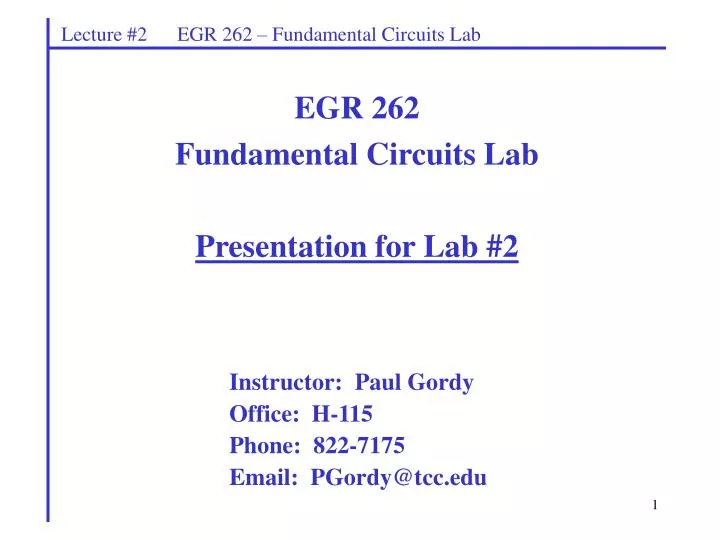
Lecture #2 EGR 262 – Fundamental Circuits Lab. EGR 262 Fundamental Circuits Lab Presentation for Lab #2. Instructor: Paul Gordy Office: H-115 Phone: 822-7175 Email: PGordy@tcc.edu. Lecture #2 EGR 262 – Fundamental Circuits Lab. Microprocessors

E N D
Lecture #2 EGR 262 – Fundamental Circuits Lab EGR 262 Fundamental Circuits Lab Presentation for Lab #2 Instructor: Paul Gordy Office: H-115 Phone: 822-7175 Email: PGordy@tcc.edu
Lecture #2 EGR 262 – Fundamental Circuits Lab • Microprocessors • A microprocessor is essentially a computer on a single chip. It is also an example of • a complex finite state machine or clocked sequential circuit. • The first microprocessor was introduced around 1970. • By 1974 the 8-bit Intel 8080 and Motorola 6800 were introduced • By 1978 the 16-bit Intel 8086 and Motorola 68000 were introduced. • Microprocessors have continued to develop to include current powerful Pentium and other microprocessors. Microprocessors versus Microcontrollers Microprocessors have continued to develop along two lines: 1) Performance – modern computers are based on powerful microprocessors where the focus is on speed and processing and storage of large amounts of data. The general public is most familiar with this type of microprocessor (such as Pentiums). 2) Integration – smaller microprocessors that include built-in memory and interface circuitry, or microcontrollers, are often integrated into applications, such as appliances, vehicles, equipment, etc. The focus here is reduced size, reduced cost, and a reduced chipset (onboard memory, for example, rather than separate memory chips). The general public is less familiar with microcontrollers, although ten times more microcontrollers are sold than microprocessors!
Lecture #2 EGR 262 – Fundamental Circuits Lab • Microcontroller evolution • Microcontrollers have continued to evolve. Using Motorola as an example: • Recall that in 1974 the Motorola 6800 was introduced • Later versions included the Motorola 6801, 6802, and 6808. • In 1985 the Motorola 68HC11 was introduced (including several versions) • In 1996 the Motorola 68HC12 was introduced. • July 2004 the Motorola microcontroller division broke off into a new company: Freescale Semiconductor, Inc • 68HC11-based applications– just to name a few: • Chrysler transmission and engine control modules • Ford digital instrument cluster • Jeep Cherokee drive and emissions control • Chevrolet engine control modules • Canon cameras • Motorola phone systems • AIM portable gas detectors • StairMaster’s exercise machines
Lecture #2 EGR 262 – Fundamental Circuits Lab Freescale Semiconductor, Inc – a few words from their web site (www.freescale.com) Freescale Semiconductor, Inc. is a global leader in the design and manufacture of embedded semiconductors for the automotive, consumer, industrial, networking and wireless markets. The privately-held company is based in Austin, Texas, and has design, research and development, manufacturing or sales operations in more than 30 countries. Freescale is one of the world's largest semiconductor companies with 2006 sales of $6.4 billion (USD). Pervasive Innovation Freescale may be one of the largest companies that people touch every day, but have never heard of. It has shipped more than 17 billion semiconductors, which can be found in everyday name brands: Motorola cell phones Sony electronics Whirlpool appliances Logitech keyboards and mice Lifefitness cardiovascular and strength training equipment Cisco routers Bose Acoustic Wave radios Trane heating and cooling equipment Mercedes, BMW, Ford, Hyundai and General Motors vehicles Market Leadership Freescale is a leader in many markets it serves: No. 1 in automotive semiconductors — Gartner No. 1 in communications processors — Gartner No. 2 in overall microcontrollers — Gartner No. 2 in digital signal processors — Forward Concepts No. 4 in wireless handset radio frequency microprocessors — iSuppli Freescale has design, research and development (R&D), manufacturing or sales operations in more than 30 countries. We have seven wholly-owned wafer fabs, two assembly and test sites and a 300-millimeter pilot line and R&D center in Crolles, France, jointly owned with STMicroelectronics and Philips. Freescale invests $1 billion annually in R&D and has 5,500 patent families. A New Life After more than 50 years as part of Motorola, Freescale started a new life as a stand-alone company in July 2004. Since then, under the leadership of Chairman and CEO Michel Mayer, the company has focused on improving financial performance, reenergizing the culture and building a global brand.
Lecture #2 EGR 262 – Fundamental Circuits Lab • Microcontroller boards • Microcontrollers are often available on circuit boards for learning and building • prototypes of designs. Microcontroller boards might contain: • Microcontroller • Crystal clock generator • Power supply (or regulator) • Input/output connections for downloading programs, reading keyboard inputs, and displaying outputs • Connection points the microcontroller’s input and output pins • Additional memory • 68HC11 Microcontroller Boards – just to name a few: • M68HC11EVBU (Motorola Evaluation Board) • 68HC11F1 by Allen Systems, Inc. (www.allen-systems.com) • Handy Board – developed and licensed by MIT (www.handyboard.com) • F68HC11 single chip evaluation board by NewMicros (www.newmicros.com) • MicroStamp11 by Technological Arts, Inc. (www.technologicalarts.com) – used in EGR262 and in this course
Lecture #2 EGR 262 – Fundamental Circuits Lab MicroStamp11 The MicroStamp11 is a microcontroller or microprocessor. It is built by Technological Arts and is based on the Motorola 68HC11 microcontroller. Technological Arts states that the MicroStamp11 is the world’s smallest microcontroller module. The MicroStamp11 is about the size of a postage stamp!
Lecture #2 EGR 262 – Fundamental Circuits Lab • MicroStamp11 Breadboard Setup • The MicroStamp 11 is easily used on a breadboard with two modules: • MicroStamp11 Module – fitted with a 20-pin connector that plugs into a breadboard • USB-to-MCU Interface Module – allows for serial communication using a USB port on a computer. The USB connection can also be used to provide power (5V) to the breadboard. A few wires are required as shown below. MicroStamp11 Module USB-to-MCU Interface Module
MicroStamp11 Breadboard Setup Transmit and Receive wires for serial communications via the USB 5V and ground from the power rails to pins 11&12 on the MicroStamp11 Module 5V and ground from the USB module to the power rails USB-to-MCU Interface Module MicroStamp11 Module
Lecture #2 EGR 262 – Fundamental Circuits Lab MicroStamp11 Features (reference: www.technologicalArts.com)
The MicroStamp11 used in EGR 262 is the Turbo version with 32k of ROM (different part number with USB connector) Lecture #2 EGR 262 – Fundamental Circuits Lab • Memory • There are two types of memory: • ROM (Read-Only Memory) – used to store permanent programs and data. Data stored in ROM is not erased when the MicroStamp11 is powered down, so programs that you save will still be in memory the next time you use the device. The MicroStamp11 has either 8k, 32k, or 64k of ROM, depending on the version of the MicroStamp11 purchased. • RAM (Random Access Memory) – used as a scratchpad to store variables during the execution of a program. Data stored in RAM is lost when the MicroStamp11 is powered down. The MicroStamp11 has only 256 bytes of RAM. Clock and Data Transfer Rate The MicroStamp11 is a digital synchronous device, meaning that all instructions are executed in synchronization with a hardware clock. The MicroStamp11 is available with either 8MHz or 9.8304 MHz (Turbo version) clock. Data can be transferred to the MicroStamp11 via the serial cable at either 9600 baud (bytes/second) or 38400 baud (Turbo version).
Lecture #2 EGR 262 – Fundamental Circuits Lab Power Source The 68HC11 is powered by a 5V DC source. We will use 5V provided through the USB connector. However, a separate 5V source can be used if desired. • Operational Modes (sliding switches) • The MicroStamp11 has two modes of operation. The modes are selecting by using • the sliding switches on the side of the MicroStamp11 module. The modes are: • Boot mode – used when programs are downloaded to the MicroStamp11. Slide the two switches together to place the MicroStamp11 in boot mode. • Run mode – used when programs are run by the MicroStamp11. Slide the two switches apart to place the MicroStamp11 in run mode.
Lecture #2 EGR 262 – Fundamental Circuits Lab External Pins The ribbon cable from the docking module gives access to the 20 pins on the MicroStamp11. The pins have different functions at different times and their use will be explored in later labs.
Crystal - 8MHz or 9.834 MHz (looks like a silver cylinder) 5V regulator Slide switches used to put the MicroStamp11 into boot mode or run mode 68HC11 microcontroller 20 pins connected to the breadboard via the ribbon cable Lecture #2 EGR 262 – Fundamental Circuits Lab MicroStamp11 Module
Lecture #2 EGR 262 – Fundamental Circuits Lab ICC11 C Compiler The MicroStamp11 will be programmed in C in this course. Note that ODU has a junior level microprocessor course (also based on the 68HC11), but assembly language programming is used in the course. We will also program the MicroStamp11 using assembly language for one lab in EGR 270. The C compiler used in the course is the ICC11 developed by ImageCraft. The compiler is only available in the H-273 lab; however, a 45-day trial version of the compiler is available on the instructor’s Blackboard site.
Lecture #2 EGR 262 – Fundamental Circuits Lab Downloader A program named MicroLoad is provided with the MicroStamp11 in order to download compiled C programs (S19 files) into the MicroStamp11.
Lecture #2 EGR 262 – Fundamental Circuits Lab Terminal Program The MicroStamp11 does not have a keyboard or display, so how do we communicate with it? We can do so using the USB port and a terminal program, such as PuTTY, TeraTermPro, or HyperTerminal (all freeware). In EGR 262 we will use PuTTY which can be easily be found for free download or from the course Bb site. It is also available on the computers in lab. Prompt from the MS11 displayed on PuTTY Inputs from keyboard displayed on PuTTY Output from the MS11 displayed on PuTTY More details on these settings for PuTTY later.
Lecture #2 EGR 262 – Fundamental Circuits Lab • Writing a C program and executing it on the MicroStamp11 • The basic steps are: • Write a C program using the ICC11 compiler. • Compile the program to produce an S19 file. • Download the S19 file to the MicroStamp11 using TurboLoad. • Run PuTTY to make a connection between your computer and the MicroStamp11 via the USB cable. • Press the reset button on the MicroStamp11 to run the program. • For more detailed instructions with screen captures, see the handout: • “Running your first program on the MicroStamp11”
Lecture #2 EGR 262 – Fundamental Circuits Lab Programming in C EGR 125 is a prerequisite for EGR 262, so a basic familiarity with C++ programming is assumed for this course. Don’t worry! You aren’t expected to be fluent in programming from the start. You will find programming help in the following areas: • Explanations and examples in the lab manual for each experiment • An appendix in the back of the manual on C Programming for the MicroStamp11 • Examples in the PowerPoint presentations given by the instructor. • Help from the instructor and your lab partner C versus C++ Many instructions are identical between C and C++, especially as we will not be doing any advanced programming (no classes, for example). Keep in mind that the MicroStamp11 does not work with real (floating point) numbers, so numerical values will typically be stored as integers. Figure 1 below from the lab manual appendix lists the types of integer and character variables that are available.
Lecture #2 EGR 262 – Fundamental Circuits Lab C Programming for the MicroStamp11 The biggest challenge is not dealing with the differences between C and C++, but learning the assortment of functions that have been written specifically for the MicroStamp11. These functions are located in the file kernel.c that is available on the instructor’s Blackboard site. Kernel functions The MicroStamp11 has no operating system. A set of functions and memory specifications has been written in the file kernel.c that will be needed in every program that you write. These functions are particularly important for input and output of information between the computer and the MicroStamp11. Standard C instructions will typically be used for processing of the data (performing calculations, making decisions, creating loops, etc.). An additional file vector.c will be needed in every program as well. It is used to define the absolute address of your program’s starting point. Several of the functions in kernel.c are explained in Chapter 2 of the lab guide. They are shown on the following pages as well.
Lecture #2 EGR 262 – Fundamental Circuits Lab Kernel function (continued)
Lecture #2 EGR 262 – Fundamental Circuits Lab Kernel function (continued)
Lecture #2 EGR 262 – Fundamental Circuits Lab Kernel function (continued)
Lecture #2 EGR 262 – Fundamental Circuits Lab Example: The following program is also used in the handout entitled “Running your first program on the MicroStamp11” . Discuss the program in detail.
Lecture #2 EGR 262 – Fundamental Circuits Lab Tasks for Lab 2: • 4.1. Pre-lab Tasks: • (1) Include a picture of Breadboard Layout (with the MicroStamp11 and USB module). • (2) Explain how to program the MicroStamp11, including: • Detailed step-by-step instructions (in your own words) for compiling a program using the ICC11 • Detailed step-by-step instructions (in your own words) for downloading a program using MicroLoad • Detailed step-by-step instructions (in your own words) for running the program using PuTTY • (3) Write a C-language calculator program for the MicroStamp11. Your program should read two unsigned integers from the PuTTY, adds these integers together, and then write the answer to the PuTTY. After doing this the program should wait until a new addition problem is entered from the PuTTY. Note:Begin each program with a section of comments including your name, course number, lab number, filename of program (Lab1.c, for example), and a brief description of the program.All programs should include plenty of comments. • (4) Your pre-lab writeup should have a listing of this program as well as an explanation of how the program works. • (5) List the min and max values (in decimal form) for signed integers and unsigned integers.
Lecture #2 EGR 262 – Fundamental Circuits Lab • 4.2. In-lab Tasks: • (1) No additional connections are required for this lab, but ask the instructor to verify that your USB and power connections are correct before proceeding. • (2) Detailed handwritten comments (like a diary) of all activities during lab. • (3) Follow the instructions in the handout “Running Your First Program on the MicroStamp11” • Run your program and verify that it is working properly. Include at least 4 examples printed from the terminal program (PuTTy), including one with a result that is greater than 65535. Also test your program with negative numbers as inputs and discuss the result. • 4.3. Post-Lab Tasks: • (1) Demonstrate the functionality of your program to the instructor and have the instructor double check the completeness of your lab book. Your lab-book should contain your answers to the pre-lab tasks as well as a listing of the final program that you obtained during the In-lab task. • (2) Your post-lab portion of the lab book should contain the final program listing you ended up with. • (3) You will need to explain the differences between your pre-lab and postlab programs. You will need to explain why these changes were made. • (4) Explain the answer for the example that was greater than 65535. • (5) Discuss how well the program works and any limitations to the program.