Download
1 / 1
10 likes | 119 Views
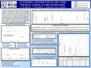
A SYSTEMATIC CONSTRUCTION OF LDPC CODES FOR RELAY CHANNEL IN TIME-DIVISION MODE A. de Baynast, A. Chakrabarti, A. Sabharwal and B. Aazhang. Gains due to relaying (relay midway between source, destination. Channel attenuation exponent = 2).

E N D
A SYSTEMATIC CONSTRUCTION OF LDPC CODES FOR RELAY CHANNEL IN TIME-DIVISION MODE A. de Baynast, A. Chakrabarti, A. Sabharwal and B. Aazhang Gains due to relaying (relay midway between source, destination. Channel attenuation exponent = 2) We address the problem of LDPC code design for relay channel in time-division mode based on a distributed strategy: In the first time slot, the source transmits part of the codeword. The relay and the destination receive it but only the relay can decode it. In the second time slot, the relay transmits the additional redundant bits to the destination. The destination is able to decode the transmitted codeword based on the data received in both time slots. The asymptotic performance of the LDPC codes that we designed are as close as 0.6 decibel from the theoretical limit. Relaying and Half Duplex Relaying Decode-and-Forward Relaying Broadcast mode: S broadcasts. R receives and decodes. D cannot decode, but stores signal. N1 bits transmitted. Multiple Access mode: R+S transmit additional parity bits for the information bits that were sent in BC mode. D decodes using the signal received in BC mode as well as the current (MAC mode) signal. (N-N1) bits transmitted. Structure of overall parity check matrix H Thresholds and BER performance of a rate-1/2 relay code H11(N1-RN)N1 0(N1-RN)(N-N1) H21(N-N1)N1 H22(N-N1)(N-N1) H11 is the parity check matrix of a code that is decodable at the relay but not at the destination. The code for H should be decodable at the destination. Why relaying? Higher throughput with same total power. Why half-duplex? Difficulty of accurate interference cancellation. Density Evolution for relay parity check matrices 1. Stability Condition for relay and overall code 2. Degree constraints between relay, overall code The number of 1’s in any column of H11 cannot exceed the number of 1’s in the same column of H. • Relay channel parameters: • BC mode time fraction t • MAC mode correlation • Power allocation among nodes/modes