Upper Limb Prosthetic Redesign
Upper Limb Prosthetic Redesign Cassandra Edwards 1 , Meg Stevenson 1 , Amy Thomas 1 , and Meagan Williams 1 Advisors: Mark Richter, Ph.D. 2 , Paul King, Ph.D. 1 , and Aaron Fitzsimmons, CP,OTR 3 1 Department of Biomedical Engineering, Vanderbilt University, Nashville, TN

Upper Limb Prosthetic Redesign
E N D
Presentation Transcript
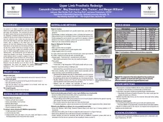
Upper Limb Prosthetic Redesign Cassandra Edwards1, Meg Stevenson1, Amy Thomas1, and Meagan Williams1 Advisors: Mark Richter, Ph.D.2, Paul King, Ph.D.1, and Aaron Fitzsimmons, CP,OTR3 1Department of Biomedical Engineering, Vanderbilt University, Nashville, TN 2Max Mobility, Nashville, TN 3The Surgical Clinic, Nashville, TN BACKGROUND MATERIALS AND METHODS DEVICE DESIGN Our project is to design or modify an already existing design of an upper limb prosthesis for a nine year old boy with upper limb deformities. This prosthesis will address the specific needs of the boy we are working with since we are designing a prosthesis specifically for him. The key problem for the boy is that he has two shortened arms. He was born without an ulna in either arm and only has a thumb and index finger on each hand. Although he has a forearm, there is webbing at the elbow joint, which prevents him from fully extending his arms. Because of these factors, he has limited use of his elbows and fingers. He also has a smaller frame than an average nine year old. He currently has an upper limb prosthesis which is used for limited independent dressing as well as some reaching tasks. The prosthesis fits over his "elbow" and restricts any utilization of his hands. The drawback to the current design is that he is unable to engage in many of the activities that he used to be able to do, such as typing. In order to still be able to do these tasks, he must take the prosthesis on and off several times during the day. Because of his arm structure, he is not able to do this independently. This project will redesign the existing prosthesis to make it more functional for an active nine year old boy. • Steps for Casting • Roll saran wrap around patient’s arm, position plastic tube, cover with a wet stockinet • Dip fiberglass or plaster casting tape in clean, cold water and squeeze out • Wrap around his arm no more than 3 times so it does not become too thick • Gently massage the cast to smooth it out, careful not to squeeze or distort it • Draw line over tube to cut along in order to line up cast once removed • Make sure cast is fully set before cutting it off • Steps for Making the Test Socket • Cast the arm • Make a positive mold out of plaster • Pull plastic over positive mold to create negative mold • Shape negative mold to fit correctly • Four test sockets were made from the mold and each socket was tested for fit on Matt—needed to be flush with skin, not painfully tight. • Original plastic: ThermolynSoft, manufactured by Otto Bock • More flexible and easier to form onto very small mold shapes • Final socket • 3/16" thickness • Vivakplastic, a high temperature PETG plastic-plastic with zero creep • Tested for myoelectric activity in Matthew's arm. • Determined there was activity because he could open and close a hand • Next used a MyoBoy, which measures patient muscle potentials with the same electrodes used in the definitive prosthesis. • Determined that Matthew was able to independently control his muscles • The targeted muscles were the flexors and extensors in his forearms. His physiology did not allow for the traditional use of the bicep and tricep. • MyoBoy Software includes a fun "racecar" training module that helps to train the patient for their device before they are fitted. • Matthew uses the software and electrodes at home to practice contracting muscles to properly control MyoBock hand. a a Table 1. Cost breakdown of Ottobock hand and elbow components. Figure 2. a) Casting Matthew’s arm; b) Creating test socket from mold. b b Figure 1: a) Matthew b) The current prosthetic. PROJECT GOALS • Mother’s main goal: • Give him the ability to dress independently and use the restroom on his own. • Our short-term goals: • More useful for him in general as well as give him the desire to use it • Have the potential for growth • Give him the ability to put the prosthetic on by himself, which was very difficult with his existing prosthetic • Our long-term goals: • Him eventually to be able to live on his own Figure 3. MyoBoy Software for determining and developing muscle control. FUTURE DIRECTIONS • Did not want to overwhelm Matthew with too many components, • Decided to only introduce a myoelectrically controlled hand • In the future, may want to introduce a myoelectrically controlled elbow • Specifically the MyobockErgoArm Electronic Plus, which would give him greater and easier use of his arm • Matthew must first learn how to use the electronic hand well before adding any new component • Meeting our original goals • Accomplishing reaching tasks will be put on hold until mastering hand • Eventual addition of myoelectrically controlled elbow will broaden abilities • Results in a better product in the long run, but requires work and practice on Matthew and his family’s part. DEVICE DESIGN • Used an electrically powered hand in order to give Matthew more functionality • Chose the OttobockElectrohand 2000, which is myoelectrically controlled • Benefits of using this particular myoelectric hand: • Dynamic Mode Control (DMC) which allows the level of muscle signal to determine the speed of opening and closing of the hand, as well as the grip force. • More closely mimics the natural hand over other electrical hands • For aesthetic purposes, a glove can be placed over the hand to make it appear more like a natural hand • Wanted to give Matthew an elbow so he can accomplish more tasks • Chose the Ottobock 12K19 Body Powered Passive Elbow Lock which has 10 locking positions in 8o increments • Will allow him to either push a button to release the elbow and lock it or a figure 9 harness • Elbow will be attached to the socket device that goes over Matthew’s arm • Socket interface will hold the electrodes that will pick up Matthew’s myoelectric pulses which will be laminated in the final device to prevent air from escaping to create a suction fit. MATERIALS AND METHODS • Possible ideas for his device: • Humeral cuff with Velcro closure • Stump sock interface over humerus • External elbow hinges • Myobock hand with myoelectric interface • Figure 9 suspension system • To design a device that would fit Matthew appropriately: • A cast was made of his arm • A test socket was made • Measurements were also taken of his arm, hand, and fingers to ensure that appropriately sized components were ordered Figure 4: The components of the device aligned how they would be put together. Included is an electric hand with a glove over it to show the difference between a gloved and non-gloved electronic hand. ACKNOWLEDGEMENTS We worked with the permission of Matthew’s parents and in collaboration with Aaron Fitzsimmons, CP, OTR.