New Conductive Structure for Electrodynamic Bearings
260 likes | 444 Views
LAB. DE SYST. ROBOTIQUES. New Conductive Structure for Electrodynamic Bearings. Ding Guoping Wuhan Univ. of Techn. Jan Sandtner Hannes Bleuler. Context: Magnetic Bearings. « Active » M.B. AMB Electromagnets Feedback Control

New Conductive Structure for Electrodynamic Bearings
E N D
Presentation Transcript
LAB. DE SYST. ROBOTIQUES New Conductive Structure for Electrodynamic Bearings Ding Guoping Wuhan Univ. of Techn. Jan Sandtner Hannes Bleuler
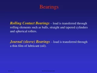
Context: Magnetic Bearings • « Active » M.B. AMB Electromagnets Feedback Control • « Passive » M.B. PMB Unstable equilibrium at rest (Earnshaw)
Context: MagneticBearings • « Active » M.B. AMB Electromagnets Feedback Control • « Passive » M.B. PMB Unstable equilibrium at rest (Earnshaw) Stabilization with additional effect– Gyroscopic– Electrodynamic (eddy currents)
Passive MB: No loss at nominal position possible! Assumptions: • Perfectrotationalsymmetry of magnetic flux • Perfect alignement of geometric, magnetic and intertial axis • No external vibrations • Operation in vacuum
Example: ELECRODYNAMIC PASSIVE MAGNETIC BEARING TEST RIG ASSEMBLY 1.3 kg rotor (wires just for monitoring measmt.) ISMB 9 (2004)
permanent magnet rings as radial bearings (in an attractive mode) ➙ unstable in thrust direction ➙ electrodynamic system as an axial bearing (with two planar Halbach arrays)
Upper touch-down bearing Weight compensation Upper radial bearing Motor magnets Halbach arrays Motor magnets Lower radial bearing Lower touch-down bearing Rotor length ca 40 cm, 1.3 kg
Touch-down bearing Weight compensation Damping discs Radial bearing Damping discs Motor coils Axial bearing coils Motor coils Damping discs Radial bearing Touch-down bearing STATOR ASSEMBLY
THRUST BEARINGS Two stationary sets of four coils are located at the middle of the air gap between the arrays There are two coil plates in a close axial contact, each containing four coils connected with appropriate polarity in series Coils of both plates are connected in series with and then short-circuited.
AXIALLY DISPLACED POSITION: CURRENT FLOWS DUE TO ASYMETRIC FLUX DISTRIBUTION, RESULTING IN RESTORING FORCE
RESULTS (ISMB 9 2004): • tested up to 6’000 rpm • robust to shaking or impacts. • The rotor levitates at 4’800 rpm. • Axial clearing 2mm
Further optimization 1: Reduce parasitic losses by approaching rotational symmetry
SIDE VIEW FRONTAL VIEW rotor PM back iron PM rotor conductive structure stator stator axis frontal area conductive structure Example: Stabilization of Thrust direction
copper structure no eddy currents Nominal Rotor Position: Symmetry FEMM open source
copper structure displaced rotor eddy currents
radial magnetic field azimutalcurrent axial force Eddy currents • Azimutal currents in radial magnetic field produce restoring thrust force
Improvements in order to reduce losses • Improve rotational symmetry of magnetic field
Further optimization 2: Restrict eddy currents to desired path
displaced rotor Desired eddy currents at front ends of copper cylinder –> squirrel cage
Proposal: Flexible Printed Circuit 25 sheets wound on cylinder
Measurement of induced voltage @ 1000, 1500, 2000 rpm Displacement
Conclusions • Passive electrodynamic bearing systems with low losses are feasible • Practical issues in basic design and optimization remain open, solutions are proposed • Possible applications: Flywheels, momentum wheels, textile spindles etc.