Download
1 / 17
170 likes | 195 Views
Learn how to utilize an H-Bridge Inverter as a Class D Amplifier for superior efficiency and bass amplification in audio systems. Follow step-by-step instructions and test signals for optimal performance.

E N D
EE362L, Spring 2009 H-Bridge Inverter as an Audio Amplifier
There is only one music station, so please use the signup sheet (with one-hour time slots) and be considerate of others who are waiting • Before conducting the music tests with CD player and speakers, you use any lab bench to perform the first steps in the lab document
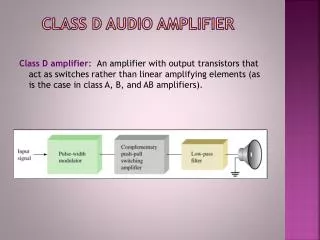
! The H-Bridge Inverter is a Class D Amplifier • Efficiency is much higher than the 50% max of a linear amplifier • But the distortion is higher than a linear amplifier • The H-Bridge works best for bass amplification and loud music • In our case, ftri = 20kHz (which should be more than 30 times fcont for best performance) • So, for best performance, fcont < 20,000 / 30 = 667Hz • ftri of 150kHz would extend the best performance range to 5kHz
Benchtop Waveform Generator Begin by Using the Benchtop Waveform Generator to Produce the 100Hz and 1kHz Vcont Signals Transformer/DBR Three Headlight Bank H-Bridge Inverter Vcont
Using 100Hz Sinewave Input Input Waveform generator output Inverter output Output Dead spots at zero crossings are characteristic of PWM because of blanking
100Hz Output, THD 2% 1 kHz span, 500 Hz center Save screen snapshot #1 FFT of inverter output with 100Hz input signal
! With 1kHz Input, the Output THD Remains 2% 10kHz span, 5kHz center Save screen snapshot #2 FFT of inverter output with 1kHz input signal
For the Music Test, Replace the Three Headlight Bank with Four Speakers The sound quality is best when loud, but do not raise Vdc above 20V or it will be too loud Use one-half of the transformer winding to power a DBR so that you don’t accidentally raise Vdc above 20V Four 8Ω speakers in series become a 32Ω load 495µF of series capacitance blocks DC current flow to the speakers
With the LC Filter and 32Ω Speaker Load, the Resonant Spike is Pronounced Gives you a treble boost – try with and without the 10µF cap
Transfer Function Without 10µF Output Capacitor (but leaving the 100µH inductor in) Roll-off due to 459µF series capacitance Roll-off due to 100µH inductor Speakers do not respond much anyway
! Use the Mono Output of a CD Player as Your Vcont Signal Two small 1:1 audio transformers at the back of the CD player add channels A and B to produce a mono Vcont signal for the H-Bridge inverter Switch channels A and B outputs to 1. the speakers, or 2. the summing transformers
iPod update • The CD player is also equipped with channel A and B auxiliary audio inputs. Use the AUX mode. • An iPod interface cable is provided so that you can play your iPOD into the CD player, and use the CD player to boost the resulting mono signal to the 3-4 volts needed for Vcont. • By itself, the iPod only produces about one-tenth of volt, which is not large enough for Vcont. • When using an iPod, turn the iPod volume to the max, and the CD player volume to the max.
Mono Signal Used as Vcont for the H-Bridge Inverter (Avoid Clipping) Signal not exceeding the 4V triangle wave peak, so ma < 1
Operation with the CD Player • Start with Vdc = 0V • Raise the CD player volume to the maximum • Raise the ma control potentiometer to the maximum • You will hear weak music with Vdc = 0 because the MOFSET gates are firing • Sound quality is best when loud. Gradually raise Vdc to 15V as long as the distortion is not excessive Input CD player Output output Inverter output Save screen snapshot #3 Top curve: Audio output of CD player to inverter, Bottom curve: Output of inverter to speakers (scope set to average over one cycle)
Use My CD or Yours • Track 1. The Hollies, “Long Cool Woman in a Black Dress” • Track 2. Eagles, “Peaceful Easy Feeling” • Track 3. America, “Sister Golden Hair” • Track 4. Electric Light Orchestra, “Don’t Bring Me Down” • Track 5. The Beach Boys, “Help Me, Rhonda” • Track 6. The Moody Blues, “Your Wildest Dreams” • Track 7. Charlie Dore, “Pilot of the Airways” • Track 7. Ronnie Milsap, “Any Day Now”
Use the Clamp-On Ammeter for Power Supply Current (be sure to zero the meter as described in the document) • The average current from 15Vdc will be about 0.1 to 0.15A • The 2-3 Watts from the DC power supply will produce a surprisingly loud output • If you are bold, you can use 20V (about 3 - 4 Watts). • And your inverter can produce 200W!