Download
1 / 22
220 likes | 234 Views
This article discusses the main improvements made in the cryogenics operation of the Large Hadron Collider (LHC) during RUN 2, including process optimization, control system updates, and results from two years of operation at 6.5 TeV. The cryogenic infrastructure, thermal load, and reliability of the LHC cryoplants are also examined. The article concludes with future perspectives and ongoing optimization efforts.

E N D
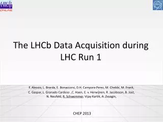
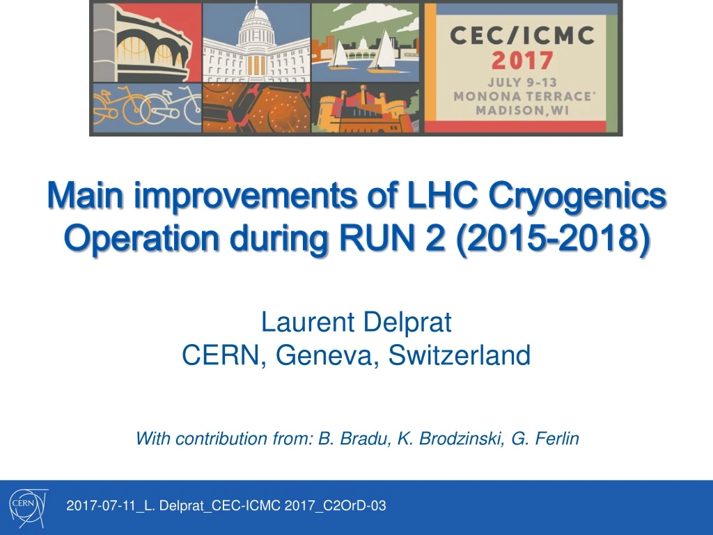
Main improvements of LHC Cryogenics Operation during RUN 2 (2015-2018) Laurent Delprat CERN, Geneva, Switzerland With contribution from: B. Bradu, K. Brodzinski, G. Ferlin 2017-07-11_L. Delprat_CEC-ICMC 2017_C2OrD-03
OUTLOOK Introduction– LHC Cryogenic System Architecture Run 2 cryogenic operation overlook Process optimization and update of the control system Results of two years of operation at 6.5 TeVConclusion– Perspectives 2017-07-11_L. Delprat_CEC-ICMC 2017_C2OrD-03 2
Cryogenic Infrastructure HL HL B A P5 LL LL A – upgraded ex-LEP cryo plant B – new LHC cryogenic plant P4 P6 LHC Cryogenics B A • LL – Low Load sector • HL – High Load sector LL LL • circumference ~ 27 km, • constructed at ~ 100 m underground, • the accelerator ring inclination is 1.4 % A P3 P7 B HL HL B LHC cryogenics: 8 x 18 kW @ 4.5 K 1800 sc magnets 24 km & 20 kW @ 1.8 K 37 000 tons @ 1.9 K 130 tons of helium inventory Compressor station P2 P8 4.5 K refrigerator P18 A Interconnection box 1.8 K pumping unit (cold compressor) P1 2017-07-11_L. Delprat_CEC-ICMC 2017_C2OrD-03 3
Run 2 Cryogenic Operation 2017-07-11_L. Delprat_CEC-ICMC 2017_C2OrD-03 4
1.9 K cooling circuit ~ 214 m subsector Screen (70 K, 1.6 Mpa) F Return (4.5 K, 0.3 Mpa) D Around 90 tons of He in cold masses ! 2017-07-11_L. Delprat_CEC-ICMC 2017_C2OrD-03 5
Thermal load on the 1.9 K circuit For one high load sector (e.g. sector 1-2): Thanks to 1.9 K heat load lower than design capacity, optimization in operation scenario could be done 2017-07-11_L. Delprat_CEC-ICMC 2017_C2OrD-03 6
Cryogenic System Configurations • Run 1 (2010-2012): operation at reduced capacity • Two 4.5 K refrigerators and two cold pumping units kept off • Run 2 (2015): high capacity required for beam screen cooling • All 4.5 K refrigerators in operation • Low 1.9 K load => 3 cold pumping units kept off => higher global availability • Run 2 (2016-17): high capacity required for beam screen cooling • All 4.5 K refrigerators in operation • 4 cold pumping units kept off In operation Compressor station Interconnection box Stopped 4.5 K refrigerator 1.8 K cold compressor 2017-07-11_L. Delprat_CEC-ICMC 2017_C2OrD-03 7
Feed-forward action on 1.9 K circuit Feed-forward regulation was applied successfully on inner triplets 1.9 K cooling loops, to smooth its thermal reaction at the beginning of collisions period and beam dump. Beam dump with FF action Beam dump without FF action Adjust beam to collision without FF action Adjust beam to collision with FF action 2017-07-11_L. Delprat_CEC-ICMC 2017_C2OrD-03 8
Dealing with thermal load @ 4.5 – 20 K Feed-forward logic + optimization of cryo maintain interlock Process optimization + adaptedcryogenic system configuration SOFTWARE HARDWARE Refrigerationcapacitywithadapteddynamics Large continuousdemand for cooling capacity Cryogenics Beam screenheatload 2017-07-11_L. Delprat_CEC-ICMC 2017_C2OrD-03 9
LHC cryoplants stops Independent stops inducingloss of cryo conditions (cryo maintain interlock = 0) 2015 2016 2017-07-11_L. Delprat_CEC-ICMC 2017_C2OrD-03 10
LHC Cryoplants Reliability Thanks to continuous efforts of operation and support teams, reliabilitywasincreasedfrom 2015 to 2016 by acting directly on the number of stops 2017-07-11_L. Delprat_CEC-ICMC 2017_C2OrD-03 11
Overall Availability RUN 2 Run 1 2017-07-11_L. Delprat_CEC-ICMC 2017_C2OrD-03 12
Helium management Preliminary 2017-07-11_L. Delprat_CEC-ICMC 2017_C2OrD-03 13
Conclusions and perspectives First two years of operation at 6.5 TeV gave extensive experience to cryogenic teams to maintain high level of availability and reduce helium losses Run 2 increased beam energy and intensity led to improvements of the cryogenics system • Process was optimized to save isothermal cooling capacity at 1.9 K. It allowed to increase the global capacity for beam screen cooling – new operation scenario was applied • Control system for beam screen and cold mass cooling loops was updated to compensate for dynamic heat load coming from the new beam parameters Optimization of the cryogenic performance is still ongoing, with upgrade of feed-forward logic on beam screens to better distribute the global cooling capacity to the local cooling loops Thank you for your attention! Questions ? 2017-07-11_L. Delprat_CEC-ICMC 2017_C2OrD-03 14
SPARE SLIDES 2017-07-11_L. Delprat_CEC-ICMC 2017_C2OrD-03
Checking refrigerators capacity Hcell power – max. 175 W ARC EH total power – max. 9300 W Dynamic test P8 QRL line C pressure Level of cold box phase separator min. 55% P7 QRL line C pressure Q6R7 EH power Q6L8 EH power 120 A Q6L8 3 losses Former LEP refrigerator tested together with sector 7-8 in March 2016 2017-07-11_L. Delprat_CEC-ICMC 2017_C2OrD-03 Spare 1 CM signal 120 A Q6L8 3 losses
Checking refrigerators capacity ARC EH total power – max. 10300 W Hcell power – max. 195 W -/+ 6 kW -/+ 2 kW -/+ 6 kW Level of cold box phase separator min. 50% P2 QRL line C pressure P3 QRL line C pressure Q6L3 EH power Q6R2 EH power CM signal Q6L3 He level 120 A Q6L8 3 losses Q6R2 120 A Former LEP refrigerator tested together with sector 2-3 in March 2016 2017-07-11_L. Delprat_CEC-ICMC 2017_C2OrD-03 Spare 2
Thermal load on the 4.5 – 20 K circuit Heat loads: Qs – static heat load, QEH – electrical heater , QBS – from beam operation (ARCs: EH is used now out of beam operation periods to avoid low velocity helium stream oscillations in BS circuit, LSS: in permanent use for stability ~50 W/sector) 85 W/half cell LHC Design Report vol. I, 2004, p.328 and p.316 K. Brodzinski et al2006 Reception tests of the cryogenic distribution line for the Large Hadron Collider (ICEC21, Prague, Czech Republic) Exercise for s1-2: Input: Qs=400 W, EH=49 W, Qqrl=630 W, Pref=7700 W, LtotBS=6033 m Calculation: (7700-1079)/6033=1.1 W/m/a -> 2*53*1.1=116 W/half cell Exercise for 2-3: Input: Qs=400 W, EH=49 W, Qqrl=570 W, Pref=7600 W, LtotBS=5971 m Calculation: (7600-1019)/5971=1.1 W/m/a -> 2*53*1.1=116 W/half cell Spare 3
Feed-forward logic on 4.5 – 20 K circuit Bradu B et al 2016 Beam screen cryogenic control improvements for the LHC run 2 (ICEC26, New Dehli, India) 2017-07-11_L. Delprat_CEC-ICMC 2017_C2OrD-03 Spare 4
Beam Screen Heating – 2016 limitations General limit of guaranteed power including transfer of capacity dedicated to 1.9 K loop Installed capacity 116 85 Design capacity 2017-07-11_L. Delprat_CEC-ICMC 2017_C2OrD-03 Spare 5
Cryogenic conditions definition • Set of cryogenic conditions: • to start powering (Cryo Start – CS) • to keep the magnets powered (Cryo Maintain – CM) 2017-07-11_L. Delprat_CEC-ICMC 2017_C2OrD-03 Spare 6