Download

1 / 24
270 likes | 1.12k Views
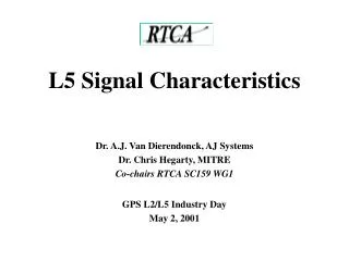
L5 Signal Characteristics. Dr. A.J. Van Dierendonck, AJ Systems Dr. Chris Hegarty, MITRE Co-chairs RTCA SC159 WG1 GPS L2/L5 Industry Day May 2, 2001. Topics. L5 Signal Design Status Characteristics Summary PN Code Structure and Properties Signal Modulation Data Structure Data Content.

E N D
L5 Signal Characteristics Dr. A.J. Van Dierendonck, AJ Systems Dr. Chris Hegarty, MITRE Co-chairs RTCA SC159 WG1 GPS L2/L5 Industry Day May 2, 2001
Topics • L5 Signal Design Status • Characteristics Summary • PN Code Structure and Properties • Signal Modulation • Data Structure • Data Content
L5 Signal Design Status • Signal design is complete • RTCA SC159 published an L5 Signal Specification • Some specification details affected by SV design included comments • Phase Noise specification • Correlation Loss specification • Detailed Received Power specification • Inter-frequency and inter-code delays • To be resolved in ICWG process as SV design evolves
L5 Characteristics - Summary • L5 = 1176.45 MHz • Bandwidth = 24 MHz (20 MHz null-to-null) • Minimum Received Power = -154 dBW • PN Code Chipping Rate = 10.23 MHz • QPSK Signal • In-Phase (I) = Data Channel • Quadraphase (Q) = Data-Free Channel • Equal Power in I and Q (-157 dBW each) • 50 bps data (rate 1/2 FEC encoded) 1176.45 MHz
L5 Codes • Codes with 2 - 13 stage shift registers • Length of one (XA code) = 8190 chips • Length of second (XB code) = 8191 chips • Exclusive-Or’d together to generate longer code • Chipping rate of 10.23 MHz • Reset with 1 ms epochs (10,230 chips) • Two codes per satellite (4096 available) • One for Data channel, one for Data-Free channel
L5 Code Performance Summary • 74 Codes have been selected • 37 I, Q pairs • Maximum non-peak autocorrelation -30 dB • Maximum cross-correlation with other selected codes -27 dB • Average autocorrelation and cross-correlation -42 dB • Maximum cross-correlation between I, Q pairs < -74.2 dB • Another pair selected as non-standard code
L5 I & Q Code and Symbol Modulation • (Coded) coherent carrier in-quadrature with data • Allows for robust code & carrier tracking with narrow pre-detection bandwidth • Independent codes to remove QPSK tracking bias
Neuman-Hoffman Codes • Encoded symbols and carrier • Modulate at PN Code epoch rate • Spreads PN Code 1 kHz spectral lines to 50 Hz spectral lines (including FEC) • Reduces effect of narrowband interference by 13 dB • Primary purpose of NH Codes • Reduces SV cross-correlation most of the time • Provides more robust symbol/bit synchronization
L5 Neuman-Hoffman Codes 10 ms Code on I 20 ms Code on I
L5 Data Content and Format • 5 – Six-Second 300-bit Messages • Format with 24-bit CRC (same as WAAS) • Encoded with Rate 1/2 FEC • To make up for 3-dB QPSK reduction • Symbols modulated with 10-bit Neuman-Hoffman Code • Messages scheduled for optimum receiver performance • Lined up with L1 sub-frame epochs
Message Content • Mostly, content is same as on L1 • Exceptions: • Group delay terms added • L5 Health added • Different Text Message • PRN number added
L5 Message Types (of 64 possible) • Message Type 1 - Ephemeris/Clock I • Message Type 2 - Ephemeris/Clock II • Message Type 3 - Ionosphere/UTC • Message Type 4 - Almanac • Message Type 5 - Text Message • Anticipated that Ephemeris/Clock Messages would be repeated every 18-24 seconds
Group Delay Considerations • GPS time defined based on L1/L2 P(Y) iono-free measurement combination • Clock correction terms in NAV data convert SV time to GPS time • C/A-to-P(Y) timing variations specified to be < 10 ns, 2s, but no corrections provided • One reason why L1/L2 C/A code will never be as accurate as L1/L2 P(Y) • L5 introduces new group delay offsets • Q: How to tie L5 into GPS time?
Satellite Group Delays C/A L1 C/A-P(Y) L1 P(Y) P(Y) L2 L2 C/A-P(Y) C/A I5 L5 Q5 DTIQ5
L5 Message Group Delay Parameters • Clock correction parameters (af05, af15, af25) provided to correct SV time to GPS L5 time • Simplest way to provide accurate time for L1 C/A-L5 users • Presumes Control Segment monitors L1 C/A and L5 • I5-to-Q5 transition offset corrected by DTIQ5 message parameter • “TGD” terms provided for single-frequency L5 users and L2-L5 users
Summary • L5 Signal Specification complete • RTCA publication in December 2000 • L5 signal and message structure provide many advanced features relative to C/A • Improved ranging precision and accuracy • Robustness in interference/low SNR conditions • Flexible message format for future growth
Special Acknowledgements • Swen Ericson, MITRE • Gary McGraw, Rockwell Collins • Peter Fyfe, Boeing • Karl Kovach, ARINC • Keith Van Dierendonck • Tom Morrissey, Zeta Associates • Tom Stansell & Charlie Cahn • Rich Keegan (Leica) • Jim Spilker