Download
1 / 34
340 likes | 438 Views
This presentation covers the design review of a project aiming to measure NO concentration and analyze dust impact energy in high altitudes. It includes subsystem definitions, prototyping plans, and project management details.

E N D
NODDEX: Nitric Oxide and Dust Detector EXperimentPreliminary Design Review Virginia Tech/Baylor University Presented by Stephen Noel December 7, 2011
PDR Presentation Content • Section 1: Mission Overview • Mission Overview • Organizational Chart • Theory and Concepts • Concept of Operations • Expected Results • Section 2: System Overview • Subsystem Definitions • Critical Interfaces • System Level Block Diagram • System/Project Level Requirement Verification Plan • User Guide Compliance • Sharing Logistics with UW
PDR Presentation Contents • Section 3: Subsystem Design • Data Logger Trade Study • NO Sensor • NO Block Diagram • PDD Risk Matrix/Mitigation • PDD • PDD Block Diagram • PDD Risk Matrix/Mitigation • IMU • IMU Block Diagram • IMU Risk Matrix/Mitigation
PDR Presentation Contents • Section 4: Prototyping Plan • NO Prototyping (or reuse) • PDD Prototyping and Testing • Section 5: Project Management Plan • Schedule • Budget • Work Breakdown Structure
Mission Overview Stephen Noel
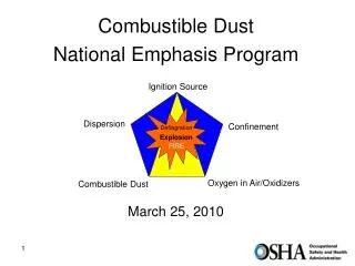
Mission Overview • Nitric Oxide (NO) sensor implementation • Measure concentration of NO as a function of altitude • Flight heritage in RockSat-C (NOIME) • Piezo Dust Detector (PDD) • Collect measurements of velocity and energy from incoming dust particles • Existing flight heritage on UT satellite
Mission Overview • Utilize Nitric Oxide sensor for NO concentration data collection in high altitudes • IMU data to accompany NO data • Optimal senor orientation • Successful data transmission and storage • Mechanical and thermal securing for reentry • Successful implementation of Piezo Dust Detector and collection of space dust impact energy readings for Baylor University • Successful data transmission and storage • Mechanical and thermal securing for reentry
Organizational Chart Graduate Advisor: Robbie Robertson Faculty Advisor: Dr. Troy Henderson
Theory and Concepts • Utilizing NO sensor and IMU from NOIME (RockSat-C flight heritage) • NO sensor collects wavelength data around 220nm • NO sensor oriented at 45 degrees to catch light off of upper atmosphere • Stepped conical shape on the inside to allow only direct rays • IMU collects acceleration, angular rate, and magnetic field data
Theory and Concepts • Piezo Dust Detector (PDD) • Little flight heritage • Stacked webs of charged wires which filter particles measuring dust velocity and energy
NODDEX ConOps (for Terrier-Orion) Altitude t ≈ 4.0 min Altitude: 95 km NO data collection t ≈ TBD Altitude: TBD Skirt Released, NO data collection Apogee t ≈ 2.8 min Altitude: ≈115 km t ≈ 4.5 min Altitude: 75 km Reentry End of Orion Burn t ≈ 0.6 min Altitude: 52 km t ≈ 5.5 min Chute Deploys -NO, IME, and PDD sensors on -Begin data collection t = 0 min t ≈ 15 min Splash Down
Expected Results • Utilizing NO sensor and IMU from NOIME (RockSat-C flight heritage) • NO sensor collects wavelength data around 220nm • Compare data to current atmospheric models • Still need expected PDD results data from Baylor University
System Overview Stephen Noel
Subsystem Overview Amplifiers IMU
System Level Block Diagram Analog
RockSat-X 2011 User’s Guide Compliance • Rough Order of Magnitude mass estimates pending • Payload components are relatively small, no layout problems expects • No deployables needed • TM connector pin allocation: Wyoming/VT TM connector: 1 Analog (pin 10) 1 RS232 Data (pin 32) 1 RS232 Ground (pin 33) Colorado TM Connector: 1 RS232 Data (pin 32) 1 RS232 Ground (pin 33) • Using two timer event pins and one GSE • CG will be kept within +/- 1 inch of center of deck • The PDD uses 3W, need to allocate power appropriately
Sharing Logistics • Payload area will be shared with UW • The AstroX team strives to test an electrically active heat shield prototype • Plan for collaboration • Team leads will stay in contact via email • SolidWorks models, mass budgets, power budgets, etc. are shared through a joint drop box account
Subsystem Design Stephen Noel
Trade Studies • Open access to spare Persistors, where as would need to purchase a third Logomatic • Logomatic requires little to no programming to initialize whereas Persistor requires working knowledge of C language • Equivalent length and width, but Persistor is approximately twice as thick as Logomatic *Most other hardware is legacy
NO: Block Diagram Analog Amplifies with a gain of ~10 Amplifies very weak signal from NO sensor
NO: Risk Matrix NO.RSK.1: Data Logger fails in-flight, Wallops telemetry data corrupted, no data received or recovered NO.RSK.2: NO pointing insufficient for data collection NO.RSK.3: NO probe does not survive heating of reentry NO.RSK.4: NO probe critically damaged by salt water exposure NO.RSK.5: NO post amplifier fails, no reliable data received NO.RSK.6: NO Femto amplifier fails, no reliable data received
PDD: Block Diagram Needs 5V and up to 3W
PDD: Risk Matrix PDD.RSK.1: Data Logger fails in-flight, Wallops telemetry data corrupted, no data received or recovered PDD.RSK.2: PDD does not provide reliable data, not calibrated correctly PDD.RSK.3: PDD does not survive heating of reentry PDD.RSK.4: PDD critically damaged by salt water exposure
IMU: Block Diagram Use less reliable serial line Convert RS482 to RS232
IMU: Risk Matrix IMU.RSK.1: Data Logger fails in-flight, Wallops telemetry data corrupted, no data received or recovered IMU.RSK.2: IMU does not provide reliable data, not calibrated correctly IMU.RSK.3: IMU does not survive heating of reentry IMU.RSK.4: IMU critically damaged by salt water exposure IMU.RSK.5: IMU transceiver fails, no data received
Prototyping Plan Stephen Noel
Prototyping Plan Risk/Concern Action Orientation of the sensor and the field of view required Verify the vertical distance to Wyoming’s plate so that it does not obstruct the field of view of the sensor. Place sensor as close to edge of plate as possible. NO sensor Concerns about testing and calibrating the PDD in the lab to determine the expected data Work with Baylor University and determine their method of calibration and expected results PDD The amplification is enough so that the outputs from Femto Amplifier is detectable Testing to make sure that the gain of the post amplifier is high enough Post Amplifier
Project Management Plan Stephen Noel
WBS (Work Breakdown Structure) NO PDD IMU • Test last year’s IMU • Decide if we will design platform for IMU similar to other years • Implement • Obtain SolidWorks drawings from Baylor • Receive and test prototype • Implement • Finish obtaining design criteria from Dr. Bailey • Redesign if necessary • Test and implement
Conclusion Questions?