2007-2008 RIT MAV Mid-Term Review
2007-2008 RIT MAV Mid-Term Review. Michael Reeder – Team Leader Kevin Hand – Lead Engineer Todd Fernandez - ME Susan Bieck – ME Jeremy Teets – ME Cody Rorick – ME Adam Bosen – CE. …where the sky is only the beginning… …and the ground is likely the end…. Put a face to the name….

2007-2008 RIT MAV Mid-Term Review
E N D
Presentation Transcript
2007-2008 RIT MAV Mid-Term Review Michael Reeder – Team Leader Kevin Hand – Lead Engineer Todd Fernandez - ME Susan Bieck – ME Jeremy Teets – ME Cody Rorick – ME Adam Bosen – CE …where the sky is only the beginning… …and the ground is likely the end…
Put a face to the name… Sue Bieck Mike Reeder Kevin Hand Jeremy Teets Todd Fernandez Cody Rorick Adam Bosen
Organizational Structure Overview of past MAV Projects Introduction/Objective of 2007-2008 RIT MAV Senior Design I deliverables Concept generation Preliminary analysis Platform design and structures analysis Propulsion system selection Airfoil selection MAV control system Design of experiments Indication of progress on deliverable completion Presentation Overview
Organizational Structure Mike Reeder- Team Leader Kevin Hand- Lead Engineer: Design of Experiments, Systems Integration Jeremy Teets -CAD Generation and Aero Structures Adam Bosen -Component Integration and Operating Software Todd Fernandez- Propulsion and Composites Sue Bieck - Airfoil Analysis and Aero Structures Cody Rorick - Flight Dynamics and Component Integration
Overview of Past MAV Projects Phase 5 Results • Objectives: • Fly 600 m • Capture an image • Obtain a reliability of 80% • Project went through 5 phases • Phase 1: Previous year’s MAV • Firefly motor • 300 mA-h battery • 6” prop • Phase 2: New Propulsion System • 3 x 2” prop • Feigao Motor produced more thrust • Phase 3: Angle of Attack (α) • Phase 4: Limiting Control Surfaces • Control surfaces determined to be a source of failure • Enabled turning but with limited success • Phase 5: Rudder Design (stiff wing) • Throttle use mimics elevator • Controlled turning in yaw reduced pilot error • 6.5” platform (longest linear dimension)
Introduction/Objectives of 2007-2008 RIT MAV • Primary Objective: • Create a Micro Aerial Vehicle, expandable in nature for future RIT research, that is simple, robust and stable in design and is capable of reading back information regarding the vehicle’s speed, angle of attack, pitch, yaw and roll rates. Flight Dynamics competition (held internationally) establishes target specifications (engineering metrics) • Max linear dimension is 80 cm • Max weight is 1 kg • Required flight time is 4 minutes • Secondary Objective: • Compete in international Flight Dynamics competition
Introduction/Objectives of 2007-2008 RIT MAV • Previous MAVs have been designed around control by an operator with a RC controller on the ground • Control systems are essential to achieving fully autonomous flight • The 2007-2008 RIT MAV will be at a level of development between being fully remote controlled and semi-autonomous with the introduction of control systems being the next step in the development process
How do we achieve… • …simplicity? • The best airfoil for the application is chosen • Fuselage/pod designed around component sizes • …robustness? • Foam wrapped in carbon fiber and fiberglass achieves robustness • Components used to be placed inside of fuselage/pod for protection • …stability? • Minimizing size of platform no longer a concern; therefore, design plane having a large wingspan with the use of winglets to improve lift • Use of recommended aspect ratio in conjunction with rear rudder, ailerons and elevators supported by “basic” flight dynamic calculations • …expandability? • Use of large platform allows for future optimization • Microcontroller increases capabilities for future research (see following slides)
Break down of MAV into subfunctions • MAV platform consists of • Airfoil and aero structures design • XFOIL analysis • Airfoil creation and flight testing • “Basic” flight dynamics calculations • Propulsion system • Motor selection • Prop selection • Battery selection • Components/electronics • Component selection • Design of experiments • Preliminary component testing • Systems integration
Senior Design I Deliverables • Platform design decided upon • Engineering metrics/product specifications completed • List of components and materials compiled • 3-D CAD model of plane created (XFOIL, Pro-E, etc.) • Foam model built based on concept generations • Experiments designed to test components’ proper functionality • Components ordered/in team’s possession • Components in possession are in test process • Foam plane is built and glide tested
Concept Generation • Started with brainstorming sessions to create various platform and propulsion ideas • Use of Pugh matrices and +, 0, - technique to narrow down spectrum of choices • Team members generated concept drawings/models on their own to emulate narrowed down choices for purposes of visualizing different platforms
Concept Generation: Selection Criteria **Results: Fixed wing design with propellers for propulsion
Concept Generation: Bill of Materials • After plane concepts were generated, a bill of materials was created reflecting the needs of the MAV
Preliminary Analysis • Creation of a stable platform required use of “basic” flight dynamic calculations • Calculations performed produced spectrum of empirically derived formulae to determine stability of platform given certain aspects of the plane design
Preliminary Analysis: Stability • Longitudinal Static Stability Criteria • Directional Static Stability Criteria • Lateral Static Stability Criteria & Where = Coefficient of Pitching Moment = Coefficient of Yawing Moment = Coefficient of Rolling Moment = Coefficient of Lift = Angle of Attack = Sideslip Angle
Preliminary Analysis: Longitudinal Static Stability & • Setting to zero and solving for lHSH you arrive at: lHSH = f( ) • Where = Downwash at 0 angle of attack. it = Tail incidence angle. iw = Wing incidence angle. = Coefficient of lift with respect to of the horizontal tail. = Coefficient of lift with respect to . Xcg = Center of gravity position along the x axis. Xac = Center of pressure position along the x axis. = Coefficient of pitching moment of the fuselage with respect to . = Coefficient of pitching moment of the wing at 0 angle of attack. = Coefficient of pitching moment of the fuselage at 0 angle of attack.
Preliminary Analysis: Directional Static Stability • Setting and solving for lH you arrive at: lH = f( ) • Where Kn = W-B interference factor. KRl = Correction factor. Sfs = Projected side area of the fuselage. lf = Length of Fuselage. d = Maximum fuselage depth Zw = Distance parallel to the z-axis, from wing root quarter chord to fuselage centerline. = Coefficient of lift with respect to alpha of the horizontal tail.
Preliminary Analysis:Lateral Stability • Setting and solving for lH you arrive at: lH = f( ) • Where bH = Wing Span. = Coefficient of lift with respect to beta of the horizontal tail. = Coefficient of lift with respect to beta of the vertical tail. = Coefficient of roll with respect to beta of the wing & body.
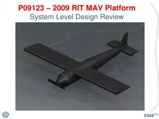
Platform Design • Initial structural choices were between a Flying wing and a conventional airframe • Due to requirements of the project, a conventional airframe was chosen (see Pugh matrices) • Wing position was chosen to be a top wing configuration for flight stability • With the deciding factor of propulsion being made, additional concept drawings were created • Two designs were generated: a simple design with a tube as a fuselage and another with a tube and blended wing portions • The blending of the wing was done to reduce turbulence effects at the wing-fuselage intersection
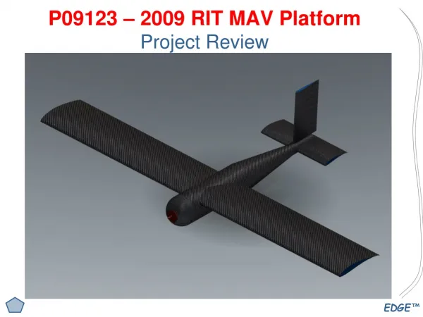
Platform Design:Prototype 1 – Pro-E Generated • 20 inch fuselage • 3 inch diameter on the fuselage at largest point • 29 ½ inch wingspan • Span on horizontal tail is 8 inches • Symmetrical airfoil on horizontal tail ¼ inch thick • Vertical tail is 4 inches tall
Structures Analysis:Design Constraints • Minimum weight • Maximum durability (crash worthiness) • Withstand estimated (and repeated) 5g crash • Withstand belly landings • Protect components from damage • Enable proper flight characteristics • Enable mounting of tail • Enable control of flight surfaces • Enable proper location of H&V tails • Minimize detrimental effect of fuselage on wing lift • Minimize drag • Provide volume for components • Allow Proper location of C.G. • Allow adjustment of C.G. location • Allow extra volume for future component expansion
Structures Analysis: Wing Structure • 12% max thickness wing • Total max thickness is 0.9608” (XFOIL determined) • Highly cambered • Planned construction • Skinned hollow structure also allows use of internal space • Flaperon to be molded as part of wing • Wing endplates manufactured separately to allow internal wing access with removal
Structures Analysis: Fuselage Construction Requirements • Separate composite structure from wing • Supports tail • Provide motor mount • Light and durable • Contain components
Propulsion System Selection • Create sufficient thrust to enable flight envelope • Speed range 0 to ~50mph • Thrust : Weight greater than 1:1 at 1kg weight level. (allowing future platform expansion) • >4min battery life at full throttle • Reserve battery capacity to support future enhancements of autonomous capabilities • Minimal system weight • Minimal system cost • Minimum Electrical Noise • System Safety
Propulsion System Selection • Determine required propeller characteristics • Pitch picked based on max speed desired • Propeller diameter picked to maximize efficiency also considering flow over the fuselage/wing • Motor selected to match propeller • Sized as small as possible to minimize weight • Motor constant selected to match prop pitch to Vmax • Motor analysis done with concern for motor heating • Motor controller chosen for motor Amax • Battery selected to match system • Series cells selected to create >=12V system • Battery selected to match single pack to amp/hour requirements • Manufacturer/design selected to allow required discharge rate with safety margin to prevent battery damage
Propulsion System Selection • Single motor • Small Brushless DC motor. • Peak Watts 120 peak current 11amps • Light, closely matches required motor constant (RPM/Volt), high quality components, small frame, integrated gearbox • Inefficient (~58%-67%) in operational envelope. Expensive, requires mount design • Single Prop • 12” diameter 8” pitch • Large enough to provide flow over wing, flow around fuselage, and flow over control surfaces at low flight speeds. • May be user safety risk, may be reliability/durability issue during landings • Speed Controller • 20 Amp max speed controller (12g weight) • Battery • 800 mAh/cell. 3.7 V/cell 20 C max discharge rate • Provides 11.1 V and 4800 mAh total capacity • Provides >8min run at full throttle/max load (vertical acceleration). Provides ~3 hours life at level cruise (~33% throttle position at Clopt) • Easily expandable for future research
Airfoil Selection: Considerations • Design Considerations • Maximize lift • Maximize airfoil efficiency (Cl/Cd) • Maximize stability • Maximize flight envelope • AOA • Velocity range • Initial metrics • Flight velocity: V=30 mph=44 ft/s • Lower limit on flight velocity: V=15 mph=44 ft/s • Angle of attack: α=5° • Elevation/atmospheric conditions: sea level @ standard atmospheric conditions • Density: r=0.00237 (slug/ft3) • Kinematic Viscosity: m=3.62x10⁻⁷ (lbf*s/ft2) • Ambient temperature: Ta=528.67 °R • Specific heat ratio: g=1.4 • Gas constant: R=1716 (ft*lbf/slug*°R) • Chord length: c=6 in=0.5 ft • Wing span: b=20 in=1.667 ft • Planform area: S=0.833 ft2 • Required lift: L=9.81 N=2.205 lbf
Airfoil Selection: Initial Selection Process/Criteria • Initial metrics used to calculate non-dimensionalized operating conditions • Equations • NASG and UIUC airfoil databases searched for any low Reynolds number airfoil listings • XFOIL viscous analysis used to analyze each of 160 possible airfoils discovered in the databases using the operating conditions relating to initial metrics • Re=144033, M=.039, a=5° • Record airfoil parameters • 3 airfoils selected for secondary analysis based on their high Cl and Cl/Cd values • Selig S1223 (Best Cl) • Eppler E62 (Best efficiency) • Selig S1210 (Balance of Cl and Cl/Cd)
Airfoil Selection: Secondary Analysis • XFOIL utilized to obtain Cl data for the highest lift airfoil (S1223) over a range of AOAs from 0° to just beyond Clmax for 1 mph increments between V=15 mph and V=30 mph • Apply the following equations to find the maximum lift at each velocity (correcting for finite wing) • The maximum lift is found to be too low for our application • Second iteration of metrics required to increase lift • c=8 in=0.667 ft • Effective span (tip-to-tip span)-(4in): b=25.5 in=2.125 ft • Reynolds number recalculated for new metrics and XFOIL utilized to obtain performance data (Cl, Cd, and Cm) on the three airfoils • Performance data analyzed with respect to lift production and efficiency
Airfoil Selection: Final Decisions • Eppler E62 • Best efficiency between a of about 2° and 5°; however efficiency drops precipitously beyond these a values • Very peaky and irregular efficiency, lift, and drag curves. Narrow range of useable a values: will decrease stability and make the plane more difficult to fly controllably • Eliminated • Selig S1210 • Highest corrected lift when operating at most efficient a • Moderate corrected Lmax in most likely flight envelope (V>=20 mph) • Best efficiency for extreme a values, moderate efficiency for moderate a values • Smooth and regular efficiency, lift, and drag curves and wide range of useable a values (easier to fly) • Selig S1223 • Highest Lmax in most likely flight envelope • Worst efficiency at moderate a values, moderate efficiency at extreme a values • Smooth and regular efficiency, lift, and drag curves and widest range of useable a values (easier to fly) • Lowest corrected lift when operating at most efficient a • Selection : Selig S1210 • 3rd iteration to metrics (based on airfoil selection) • a=6° to 7° (most efficient AOA) • Plane mass: m=500 g (based on desired velocity range)
MAV Control System: Previous Year’s 4 Maximum motors PPM motor control Manual controller transmitter receiver Servos user NTSC video camera Laptop with TV tuner transmitter receiver
MAV Control System: Advantages and Disadvantages • Advantages of previous system: • Easy to construct • Cheap • Disadvantages of previous system: • Limited motor control • Very little vehicle data • Fully manual control
MAV Control System: Proposed System 6 or 9 Maximum motors RF-232 communication Flight controller transceiver transceiver Servos Sensor suite user Laptop with TV tuner NTSC video camera receiver transmitter
Design of Experiments • Differential pressure sensor used in conjunction with a pitot tube to determine aircraft velocity • One differential pressure sensor on each wing to determine pressure difference which will yield AOA experimentally • Accelerometers placed in nose and tail to determine pitch, roll and yaw of aircraft during flight