Download
1 / 20
200 likes | 323 Views
This document outlines the design and analysis processes for high-performance magnets, focusing on magnet parameters, magnetic field quality, and mechanical considerations. It details the innovative features of the cable and coil design, including its structural components and alignment mechanisms. The magnetic analysis covers conductor peak fields and the saturation effects, complemented by thorough mechanical assessments using 2D and 3D modeling techniques. The conclusions highlight the expected performance of the HQ magnet design, demonstrating its robustness and efficiency in demanding environments.

E N D
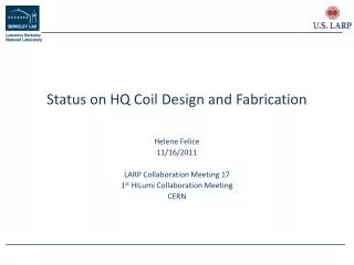
HQ design and analysis Paolo Ferracin LARP Collaboration Meeting Napa Valley, CA April 8-10, 2009
Outline • Magnet design • Magnetic analysis • Conductor peak field • Magnet parameters • Field quality and saturation effect • Mechanical analysis • Pre-load conditions • Coil and structure stress • Conclusions Paolo Ferracin
Cable and coil design • Cable • 35 strands • Width: 15.150 mm • Mid-thickness: 1.437 mm • Keystone angle: 0.750 • Insulation thick.: 0.1 mm • Coil • Aperture: 120 mm • 4 blocks • 46 turns Paolo Ferracin
Magnet designCross-section • Aluminum collars • 25 mm thick • OD = 570 mm • 4-split iron yoke • Bolted iron pads • Gaps for coil end support and cooling channels • Iron masters • 2 bladders 50 mm wide • 2 interference keys • Bolted aluminum collars for azimuthal alignment • G10 sheet between coil and collars Paolo Ferracin
Magnet design3D components • Yoke laminations, 50 mm thick with tie rods • Iron pad laminations, 50 mm thick tie rods • Collar laminations, 50 mm thick with tie rods • Iron masters • Easy insertion and removal of coil pack (large clearance) • Continuous surface • Pad-yoke alignment • Improved tolerances Paolo Ferracin
Magnet design Axial support • Stainless steel (Nitronic 40) end plate • 50 mm thick • Aluminum axial rods • 34 mm diameter • Axial pre-load provided by additional plate and piston • Piston actuated to spread apart the two end plates • Nuts to lock the pre-compression Paolo Ferracin
Magnet design Alignment • Pins shell – yoke • Master keys pad – yoke • Trapezoidal shape • Interference keys • Alignment keys • Pad – Collar • Collar – coil • Alignment keys • Under compression from assembly to excitation Paolo Ferracin
Magnet design From TQS to HQ TQS LQS HQ Paolo Ferracin
2D magnetic analysisConductor peak field and magnet parameters • Jc of 3000 A/mm2 (4.2 K, 12 T) • About 0.7 T difference between layer 1 and layer 2 Paolo Ferracin
120 T/m 2D magnetic analysisIron saturation and field quality • Rref = 40 mm • At 120 T/m • All allowed harmonics below 0.5 units • Saturation effect • b6 ± 1 unit from 0 to 20 kA Paolo Ferracin
Iron pad 3D magnetic analysisConductor peak field • Peak field in the end located on pole turn, layer 2 • Stainless steel pad over ends • About 1% lower peak field in the end with respect to straight section Paolo Ferracin
2D mechanical analysisParameters and model • Computational steps • Bladder pressurization • Key insertion • Cool-down • Excitation • Impregnated coil surfaces: bonded • All other surfaces: 0.2 friction factor • Contact pressure (or tension <20 MPa) between pole and coil • Two gradient considered • 219 T/m: limit conditions • 180 T/m: coil peak stress <150 MPa Paolo Ferracin
2D mechanical analysisBladder pressure and shell tension • Pre-loading for 180 T/m • Bladder pressure: 23 MPa • Key interference: 0.3 mm • Shell tension: • Pre-loading for 219 T/m • Bladder pressure: 46 MPa • Key interference: 0.6 mm • Shell tension: Paolo Ferracin
2D mechanical analysisCoil peak stress after cool-down • Pre-loading for 180 T/m • Coil peak stress: 150 MPa • Pole area, inner radius, layer 1 • Pre-loading for 219 T/m • Coil peak stress: 192 MPa • Pole area, inner radius, layer 1 Paolo Ferracin
2D mechanical analysisCoil peak stress with e.m. forces • Pre-loading for 180 T/m • Coil peak stress: 144 MPa • Mid-plane, inner radius, layer 1 • Pre-loading for 219 T/m • Coil peak stress: 193 MPa • Mid-plane, inner radius, layer 1 Paolo Ferracin
3D mechanical analysisParameters and model • Computational steps • Bladder pressurization • Key insertion • Cool-down • Excitation • Impregnated coil surfaces: bonded • All other surfaces: 0.2 friction factor • Contact pressure between pole and coil Paolo Ferracin
Comparison 2D-3D models Paolo Ferracin
3D mechanical analysisAluminum rod tension and coil-pole • Pre-loading for 219 T/m • E.m. force: 1372 kN • 620 kN applied at 4.2 K • <20 MPa tension at 219 T/m Paolo Ferracin
3D mechanical analysisAlignment key collar-coil • Contact between collar and alignment key Paolo Ferracin
Conclusions • HQ is a field quality quadrupole with a 120 mm bore and an expected maximum gradient • 199 T/m at 4.4 K and 219 T/m at 1.9 K • The shell based structure is based on the experience from TQS and LQS • Maintains the coil in contact with the pole in the straight section and in the end region up to short sample • Provides alignment to coil and structural components • The coil peak stress can be maintained below 150 MPa with a pre-load for 180 T/m Paolo Ferracin