Download
1 / 40
400 likes | 512 Views
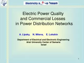
Electric Power Quality and Commercial Losses in Power Distribution Networks. A. Lipsky, N. Miteva, E. Lokshin Department of Electrical and Electronic Engineering Ariel University Center of Samaria Israel. Main sections of lecture:. Introduction .

E N D
Electric Power Quality and Commercial Losses in Power Distribution Networks • A. Lipsky, N. Miteva, E. Lokshin • Department of Electrical and ElectronicEngineering • Ariel University Center of Samaria • Israel
Main sections of lecture: • Introduction. • 2. Power flow direction. • 3. Transformer losses • 4. Method of losses reduction • 5. Conclusions
1. Introduction. One of the main issues of the European Smart Grid concept, which characterizes the power networks and systems, is the profitability of the power supply. Among other factors, it is determined by the energy losses in electric power systems.
Generation and transmission of electrical energy produced by the power system generators to its customers is characterized by technological expenditures for its transmission and distribution. These technological expenditures are called technical losses. The major share of technical losses in power networks, about 70% , refers to the distribution power networks (6-110 kV network). ~ G T1 Line T2 Load
In addition, there are losses due to the fact that the amount of electric power transmitted to the distribution network is determined by the meters of power systems, and the electric power, which is received by consumer, is determined by the meter readings of the consumers. The last component of losses belongs to the so-called commercial losses. ~ G T1 Line Thus, the total loss of electricity W can be represented in the form of two components: technical loss WТand non-technical or commercial loss WС: T2 Load
Commercial losses represent actual imbalance in the power energy in power network, which can be represented as: Where WPS is energy transferred by its source to the power network (PS - power system), WСPM is energy, fixed by consumer meter (CPM - consumer power meter), WТ is technical losses of electric power. Full power losses represent a significant values. ~ G T1 Line T2 Load
Netherlands Germany Japan Italy USA France Switzerland Spain Austria Canada New Zealand Fig.1 Power losses in power networks of different countries.
There are several known reasons of commercial losses. It should be noted that the error in determining of the technical losses also relates to business losses. One of the reasons of commercial losses is measu- rementerrors. There are known more than 30 components of the measurement errors in power supply networks. In spite of this, there is one more component of the measurement error of electrical energy that is not considered already. This component refers to the special measurement errors of power meters, caused by deteriorated electric power quality of a certain group of industrial and domestic consumers.
2. Power flow direction. What measure active energy meters of consumer which is the source of electric power quality deterioration? Let us consider for the beginning electric power consumer, which is the source of the current harmonics. LL Tr 50 Hz ~ A B BB S L Fig. 2. A typical scheme of power supply
Power distortion flowing according to the previous scheme 50 Hz E Power system symmetric С A B Load linear Fig. 4.
Further let us consider the electric power consumer, which is the source of the current fluctuations which lead to appearance of voltage fluctuations. For example, let us consider only the current fluctuations of one phase, caused by electric arc furnace. LL Tr ~ 50 Hz A B BB S EAF Fig. 5. A typical scheme of EAF power supply
2 3 1 sec The diagram of fluctuations of consumed powers Fig.6.
p.u. , Hz Fig. 8. Power spectrum of the envelope current, which modulate the impact on the fundamental current amplitude of electric arc furnace
In general, the modulating function describes a random process. To clarify the essence of the phenomenon represented modulating function as a sine wave In this case, the current in the network may be represented as Or where
After trigonometric transforms the current can be represented by the following components I.e. in the current there are components with frequencies which are not generated by energy sources of power system.
Average for the period of modulation function power loss in the resistance r is defined as I.e. the additional losses in the external source to the terminals of voltage fluctuation resistance rin p.u. defined as
Power distortion flowing for voltage fluctuation source 50 Hz E Power system symmetric С A B Load normal Fig. 9. Besides f =50±0.05 Hz
Fig. 10. AC railway connections as examples of asymmetrical load connections. Source of voltage unbalance
Source of voltage unbalance Negative sequence Zero sequence Positive sequence Fig.11.
Source of voltage unbalance Power distortion flowing for voltage unbalance source 50 Hz symmetric E Power system symmetric С A B Load normal Fig. 13. Includes f =50 Hz
~ Therefore, regardless of the type of meter, the active energy meter errors in all cases are equal to the losses in external, relative to the voltage distortion source terminals, power network on the frequencies of the current harmonics, voltage fluctuations and on frequencies of current negative and zero sequences. I.e. these are losses in the nearest power transformer and power transmission lines of primary voltage of the power transformer. T2 G T1 Line
Thus, the commercial losses of the power supply organization, are mainly determined by the losses in power transformers, which caused by distortion energy of particular source of power quality deterioration (See the next slide).
kWh meter 3. Transformer losses A typical scheme of power supply 50 Hz Fig.14. Therefore,
Estimate the losses in power transformers due to the asymmetry of the load, its oscillatory nature and its generation of current harmonics. In general case, the various types of current distortions are not constant and vary with time. The use of spectral methods for the calculation of losses in this case requires the frequency separation of currents and voltages distortions. The following is a proposal for such a frequency separation of different types of distortions.
The losses in the transformer according to the various types of current distortions on the basis of spectral methods in general can be evaluated as: Consider the simplest methods of losses calculations in transformers due to the distortions of currents and voltages of different types. They allow you to evaluate the state of the problem.
Considering the current distortions as random processes, the average loss in power transformers due to the asymmetry of the current is defined as: Where are expectation value and standard deviation of process, is transformer rated current, is s.c. transformer loss, (kW).
Neglecting the dependence of the transformer resistance on the frequency for frequencies below 75 Hz, this formula can define and the transformer losses due to the oscillatory nature of the load. It is much more difficult to determine the losses in the power transformer due to current harmonics generated by the nonlinear loads.
It is known that load losses of the current harmonics in power transformers are determined as: Where is loss due to resistance of winding for dc current, is winding eddy current loss, is other stray losses in structural parts of transformer such as tank, clams and so on. Some the results of losses calculations taking into consideration these components are shown below.
Transformer data Fig. 16. Liquid filled transformer The power losses due to harmonics are calculated according to С57.110-2008 standard
Some results of power losses calculations I Fig. 17. 1.1% 1.1%
k-factor 13 Graph of transformer loss versus current harmonics Fig. 18.
Estimate of losses magnitude Estimated transformer population in the world (February 2005) “… Nowadays, over 50% of load is non-linear. For example the are computers, energy saving lights, office equipment, variable speed drives…”
For example, Japan's commercial losses as losses in transformers only due to current harmonics can be estimated as (cos φ ≈ 1): = 900 GW × (0.5×0.01×0.7) = 3.5 GW. When load factor is equal to 0.7 . It is power of two good power stations. In general, commercial losses of power supply organization due to only the current harmonics can be estimated as: Measurement and taken into account of thecommercial losses.
4. A method for commercial losses reduction The carried out analysis of the commercial losses allows to conclude, that one of the ways to reduce these losses (may) can be the reduction of current harmonic levels generated by their sources in the supply network. This can be accomplished in many ways, including using current harmonic filters. Reducing power losses of current harmonics in power transformers of consumers’ networks and external power supply network also reduces technical losses in power networks. I.e. losses at a frequency of 50 Hz.
Consider the expression of the energy balance for produced and consumed in a power network with a source of the current harmonics in the following form: is energy consumed by this customer at 50 Hz, Here is energy produced by generators to supply a specific consumer except of own energy producer needs, is technical loss associated with electricity supply of consumers, which has equivalent just the same power and that it is not a source of current harmonics,
is an equivalent value of the energy distortion, which must produce the energy source at 50 Hz frequency. are loss of energy at 50 Hz frequency, associated with the transportation equivalent value of the distortion energy at 50 Hz to the consumer, and the loss of energy due to their generation of current harmonic source;
Thus, the power system total losses for power supply of the power consumer, which is current harmonic source, by more than 2 times higher than the power transformer losses due to current harmonics. Reducing the levels of the current harmonics in the limit up to zero, i.e. assuming one can reduce the amount of commercial and technical losses at least by twice to the losses in the power transformer and the external network users due to harmonics.
5. Conclusion 1. The power transformer losses of consumers, worsening the electric power quality, are commercial losses of power supplying organizations. 2. Reducing of these losses is possible by reduction of the levels of current harmonic, current unbalance and smoothing the load curve of specific consumers. 3. Reduction of this type of commercial losses leads to a technical losses decrease. 4. There are relatively simple methods of calculation and taking into consideration of this kind of commercial losses .