CH04 Capturing the Requirements
CH04 Capturing the Requirements. Understanding what the customers and users expect the system to do * The Requirements Process * Types of Requirements * Characteristics of Requirements * How to Express Requirements. TECH Computer Science. Capturing the Requirements (continue).


CH04 Capturing the Requirements
E N D
Presentation Transcript
CH04 Capturing the Requirements • Understanding what the customers and users expect the system to do • * The Requirements Process • * Types of Requirements • * Characteristics of Requirements • * How to Express Requirements TECH Computer Science
Capturing the Requirements (continue) • Additional Requirements Notations • Prototyping Requirements • Requirements Documentation • Participants in the Requirements Process • Requirements Validation • Measuring Requirements • Choosing a Requirements Specification Technique
Requirements • A requirement is a feature of the system or • a description of something the system is capable of doing in order to fulfill the system’s purpose. • Three categories of requirements • (1) absolutely must be met • (2) are highly desirable but not necessary • (3) are possible but could be eliminated
Why are requirements important? • The causes of failed projects (case study) • 1. Incomplete requirements (13.1%) • 2. Lack of user involvement (12.4%) • 3. Lack of resources (10.6%) • 4. Unrealistic expectations (9.9%) • 5. Lack of executive support (9.3%) • 6. Changing requirements and specifications (8.7%) • 7. Lack of planning (8.1%) • 8. System no longer needed (7.5%)
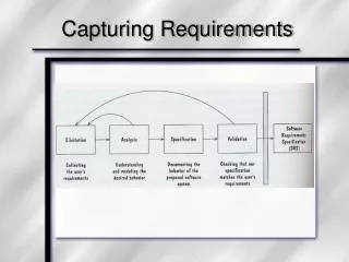
REQUIREMENTS DEFINITION AND SPECIFICATION REQUIREMENTS ELICITATION AND ANALYSIS Documentation and validation Problem analysis Problem description Prototyping and testing Are we using the right techniques or views? Have we captured all the user need? Is this function feasible? Have we captured what the user expects? The Requirements Process
Requirements vs. Design • requirements identify the what (the problem) of the system • design identify the how (the solution) • implementation-specific descriptions are not considered to be requirement unless mandated by the customer
Require- ments elicitation and analysis Design Imple- mentation Verification Require- ments definition Purpose and goals Problem Design components and use cases Code components and unit tests Problem under- standing Specifi- cations Test data and scripts Understanding of the application domain and the problem Problem-solving and Software development
Configuration Management • Tracing the correspondences in the development process • requirements that define what the system should do • design modules that are generated from the requirements • program code that implements the design • tests that verify the functionality of the system • the documents that describe the system
Functional and Nonfunctional Requirements • A functional requirement describes an interaction between the system and its environment. • A nonfunctional requirement or constraint describes a restriction on the system that limits our choices for constructing a solution to the problem.
Requirements Documents • Requirements definition is a complete listing of everything the customer expects the proposed system to do. • Requirements specification restates the requirements definition in technical terms appropriate for the development of a system design. • Formal requirements elicitation, using the same language and the same meanings
Making Requirements Testable • Specify a quantitative description for each adverb and adjective so that the meaning of qualifiers is clear and unambiguous. • Replace pronouns with specific names of entities. • Make sure that every noun is defined in exactly one place in the requirements documents.
Types of Requirements • Physical Environment • Interfaces • Users and Human Factors • Functionality • Documentation • Data • Resources • Security • Quality Assurance
Activities to find out what the customer wants: • review the current situation • apprentice with the user to understand context problems and relationships • make a video to show how the new system might work • dig through existing documents • brainstorm with current and potential users • observe structures and patterns
Characteristics of Requirements • Check the requirements to insure • correct • consistent • complete • realistic • needed • verifiable • traceable
Checking for Completeness and Consistency • Truth Table • e.g. binary variable A, B, • define And function F • All cases • A, B, F • 0, 0, 0 • 0, 1, 0 • 1, 0, 0 • 1, 1, 1
How to Express Requirements • Use formal notation to describe the system to be built • Static Descriptions • specify objects and their relationships with each other • Dynamic Descriptions • specify states and transitions between states over time
Static Descriptions • Indirect Reference • Recurrence Relations • Axiomatic Definition • Expression as a Language • Data Abstraction
Indirect Reference • implied but not stated directly • Pointing to pointer, e.g. • A points to P • where P is a pointer to something
Recurrence Relations • an initial condition is defined • the transformation from one condition to the next is expressed in terms of previously defined conditions • Fibonacci numbers e.g. • F(0) = 1 • F(1) = 1 • F(n+1) = F(n) + F(n-1) for n = 1, 2, 3, ...
Axiomatic Definition • Axiom • a set of objects • a set of operations • Generate Theorems • use axiom to generate more objects • Prove Theorems • reduce (trace) a theorem down to axiom
Expression as a Language • Use formal languages • Backus-Naur form, e.g. • ASCII characters • <digit> ::= 0 | 1 | 2 | 3 | 4 | 5 | 6 | 7 | 8 | 9 • <addop> ::= + | -
Data Abstraction • Data manipulated by a system determine the kinds of actions taken • Data abstraction is a technique to describing what data are for. • To categorize data (objects) and group like elements together forming data types (class) • Each object is then considered to be an instance of the class to which it belongs.
Methods • actions permissible with the data and data types • methods manipulate the data: • states in which the data can be, • operations to establish new states • probes to report information about state
Student Student number Credit-hours Compute tuition Out-of-state student In-state student Student number Student number Out-of-state rate In-state rate Compute tuition Compute tuition Relationships between data types (classes) • Class name • Attributes • Methods • Generalization
Dynamic Descriptions • Decision Tables • Functional Descriptions and Transition Diagrams • Event Tables • Petri Nets • Object-oriented specification
Decision Tables • a set of possible conditions at a given time • rules for reacting when certain conditions met • actions to be taken • e.g. Rule 1 • High standardized exam scores T • High grades * • A: Send admission forms =
Functional Descriptions and Transition Diagrams • A set of states, S • A initial state, s0 • A set of inputs, I • A state transition function, F • A output function, H
X (a) S1 S2 0 1 0 (b) S1 S2 1 1 0 S3 Transition among States
(Null) Requested On waiting list Confirmed Used Canceled Archived Fence diagram showing state transitions
condition action S1 S2 I/O or Condition/action
Null room request none room available decrement room count no room available put on list Requested room available decrement room count Confirmed On waiting list customer moves in none customer gives up remove from list customer cancels increment room count Used Canceled customer pays increment room count Archived Transition Diagram e.g.
Event Tables (State Tables) • Tabulate state transitions • input • State 0 1 • s0 s1, a1 s0, a0 • s1 s0, a0 s1, a0
Petri Nets • describe parallel processing • describe synchronization • tokens: each state is associated with a set of tokens • firing rules: each firing rule expresses how tokens are associated with a state; when the correct number and type of tokens are present in one state, tokens are released to travel to another state.
Event A S (a) Event 1 Event 2 (b) A S . . Event N S1 Event 1 . . . . (c) A SM Event N Three types of transitions
(a) (b) Tokens associated with firing rules
Object-oriented specification • focuses on the entities involved rather than on input/output transformation. • Extending data-abstraction to ask • What data structures define an entity? • How does an entity’s state evolve over time? • What aspects of entities are persistent over time?
Object and Method • Each entity in the system is an object. • A method is an action that either can be performed by the object or can happen to the object. • Only the methods of an object can change the state of the object. • A method can be invoked only by sending the object a message. • Encapsulation, Class Hierarchies, Inheritance, and Polymorphism.
Encapsulation • forming a protective boundary • one object has no access to internal representation of other objects • objects “talk” to other objects by message
Person College student Graduate student Out-of-state student Undergraduate In-state student Out-of-state undergraduate Class Hierarchies and Inheritance
Polymorphism // • A method is polymorphic if it is defined for more than one object. • One method for computing area, e.g. • for triangle objects • for circle objects
Additional Requirements Notations • Hierarchical Techniques • Data Flow Diagrams • Software Requirements Engineering Methodology • Structured Analysis and Design Technique • Z
Non-prescription products + Available pharmaceu- ticals { Products requiring a prescription Barbiturates (n1) Narcotics (n2) Steroids (n3) Other Hierarchical Techniques
Data Flow Diagrams • considering the system as a transformer of data • how data flow into the system, • how they are transformed, and • how they leave the system • data store is a database • An actor is an entity that provides or receives data
Data out Data in (a) Process Data store Data in Data in (b) Process Symbols in data flow diagrams
Symptoms Medical experience and knowledge Diagnosis Physical exam Medication Physician List of tests, services performed Patient history Diagnosis Accounting Bill Tests and services Patient records Prices Patient Accounting records Data flow diagram e.g.
Software Requirements Engineering Methodology • views the system as a finite-state machine • writing requirements using a Requirements Statement Language • describes the flow of processing in terms of what events initiate which processes • analyzing the requirements using Requirements Engineering Validation System • produces variety of reports, simulates the critical processing of the system
Requirements Statement Language • first uses a flow-chart type graph called R-net to • (plus) indicates a condition for branch • (ampersand) indicates parallel processing in any order • (triangles) indicates points of synchronization • (validation point*) indicates a point for taking measurement • next translate the components of R-net into statements
Account request record Extract dates + Find account records Record transaction * & Compute checking balance Compute savings balance Compute money market balance & Print balances * A requirements network (R-net)
Requirements Engineering Validation System • simulates the processing of the system • depicts flow of data with a graphics package • produces variety of reports
Structured Analysis and Design Technique • Structured Analysis represents a system with an ordered set of diagrams • each diagram represents a transformation, and at most six diagrams are used to describe a function • Design Technique explains how to interpret the diagrams