Download
1 / 1
20 likes | 180 Views
PBL2. PBL1. PBL3. U. IBL1. IBL2. z 03. z 02. z 01. ANALYTICAL MODELLING OF LARGE WIND FARM CLUSTERS R.Barthelmie, S.Pryor , S. Frandsen, S. Larsen & M. Thøgersen* Wind Energy Department, Risø National Laboratory, 4000 Roskilde, Denmark (r.barthelmie@risoe.dk)

E N D
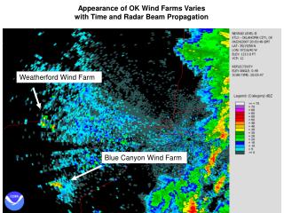
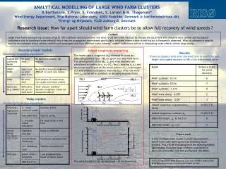
PBL2 PBL1 PBL3 U IBL1 IBL2 z03 z02 z01 ANALYTICAL MODELLING OF LARGE WIND FARM CLUSTERS R.Barthelmie, S.Pryor, S. Frandsen, S. Larsen & M. Thøgersen* Wind Energy Department, Risø National Laboratory, 4000 Roskilde, Denmark (r.barthelmie@risoe.dk) *Energi- og Miljødata, 9220 Aalborg Ø, Denmark Research issue: How far apart should wind farm clusters be to allow full recovery of wind speeds ? Context Large wind farms (comprising clusters of up to 100 turbines) constructed over the next 10-20 years will interact to change the local flow (via reduced wind speeds and increased turbulence due to combined wake effects) which may be propagated downstream particularly offshore where stable stratification is frequently observed. What is unknown is exactly how far downstream these velocity deficits will propagate and how efficient wake induced ’added’ turbulence will be in dissipating wake effects within large arrays. Boundary-layer models Added roughness modelling The model uses a roughness (z0) element to cause an internal boundary layer (IBL) to grow over the wind farm. The development of the IBL, z0 and wind recovery are calculated according to ct (ct=CT/8srsf),spacing (sr,sf) and the thrust coefficient of the wind turbines (CT), hub-height (ht) and ambient turbulence intensity (I01). After the wind farm z0 can be set as constant or decaying exponentially. The velocity deficit can be advected >10 km downwind. Results Shown as distance (km) after the wind farm at which the hub-height wind speed recovers to 98% of its free-stream value Complexity/Computing requirement Wake models Complexity/Computing requirement Future work A new multiple wake model is under development which links wake development to boundary-layer physics. This will be evaluated with the existing models against data from the large offshore wind farms in Denmark (Horns Rev 160 MW and Nysted 158.4MW). Acknowledgement: PSO Storpark contract (101991) (F&U 2104) & to Ebba Dellwik for bringing the poster to Kiev.