Download
1 / 16
160 likes | 312 Views
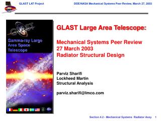
Gamma-ray Large Area Space Telescope. GLAST Large Area Telescope: Mechanical Systems Peer Review 27 March 2003 Radiator Structural Design Parviz Sharifi Lockheed Martin Structural Analysis parviz.sharifi@lmco.com. Radiator Level IV Design and Structural Requirements.

E N D
Gamma-ray Large Area Space Telescope GLAST Large Area Telescope: Mechanical Systems Peer Review 27 March 2003 Radiator Structural Design Parviz Sharifi Lockheed Martin Structural Analysis parviz.sharifi@lmco.com
Radiator Level IV Design and Structural Requirements Based on: Radiator Level IV Design Specification, LAT-SS-00394-1-D6, Draft, Dated 5 Mar 2003 LAT Mechanical Systems Interface Definition Dwg, Radiator-LAT Interface, LAT-DS-01221, Draft, Dated 25 Feb 2003 Verification Methods A: Analysis, I: Inspection, T: Test
Edge Member VCHP Reservoirs 6 PLs Axial Tie Downs 2 PLs Y X Shaded Areas Higher Densidy Core Heat Pipes 6 PLs Finite Element Model of Radiator • Honeycomb sandwich construction • Modeled using 3 layer sandwich plate-shell elements • Captures core shear deformation effects • Heat pipes • Modeled using beam elements • Panel end-member and brackets • Modeled using beam elements • Tie downs • Modeled using grounded springs • Bolted connections • Modeled with grounded or zero-length springs • Model Size: • Nodes 4840 • Shell elements: 4284 • Beam elements: 564 • Spring Elements: 38 • Analysis Weight: 36.0 kg (79.3lb) per radiator Radiator FEA Mesh Coordinate axes indicate the Radiator Panel coordinate system, for use in FEA modeling
End Member Tie Downs, 2 PLs Z Y Heat Pipes Bolted to Patch-Plate, 6 PLs End Fully Restrained Bracket, 2 PLs Finite Element Model of Radiator X Isometric View of Radiator FEA Model Coordinate axes indicate the Radiator Panel coordinate system, for use in FEA modeling
Launch Load Environment • Primary structure loads • Static Equivalent • Acceleration loads from Radiator Level-IV LAT-SS-00394-1 (3/5/03) • X-direction (transverse): ±3.375 g, • Y-direction (thrust): ± 8.5 g, • Z-direction (normal): ± 1.25 (1.7g + AF) • Sinusoidal Vibration • Preliminary load cycle results indicate accelerations are enveloped by current specification limits • Random vibration Acoustic loads • Finite element vibro-acoustic analysisperformed to define 3-sigma static-equivalent acceleration due to acousticloads on the Radiator panel • Acoustic spectrum from RadiatorLevel-IV Spec • Normal Load Factor = 25g x 1.2 (MUF) = 30g • Revised Acoustic Levels (Fig.) producelower load factors Static-Equivalent Accelerations under Launch Environment (Panel Coords) Change in Acoustic Levels from PDR Coordinate axes indicate the Radiator Panel coordinate system, for use in FEA modeling
Revised Launch Load Environment • Revised Acoustic Loads analysis • Single support system at radiator CG • Reactive loads indicate lower normal loads but higher in-plane loads
Revised Launch Load Environment • Revised Acoustic Environment produces lower normal loads, but higher in-plane loads • Stress analysis of the Radiator under the new combined load factors indicates somewhat smaller margins at all locations
Modal Analysis, First 5 Stowed Frequencies • All stowed frequencies are above the 50 Hz requirement Radiator First Five Natural Frequencies Coordinate axes indicate the Radiator Panel coordinate system, for use in FEA modeling
Panel Mode Shapes Normal Mode 1, f1 = 61.6 Hz, 1st YZ Bending Mode Normal Mode 2, f2 = 66.8 Hz, 1st XZ Bending Mode
Panel Mode Shapes Mode 4, f4 = 112.8 Hz, 2nd YZ Bending Mode Normal Mode 3, f3 = 92.0 Hz, 1st Twisting Mode Normal Mode 5, f5 = 118.1 Hz, 2nd Twisting Mode
Radiator Deformed Shape Under Launch Loads Max Normal Disp = 1.8 mm Deformed Shape Under Launch Loads
Stress Analysis Results—Face Sheet Margins • Facesheet stress analysis indicates positive margins of safety for all high-stress regions • Facesheet material properties • Material: 6061-T6 aluminum (Top: 0.060” thk, Btm: 0.030” thk) • Ftu = 296 MPa (43 ksi) • Fty = 255 MPa (37 ksi) Facesheet Stresses and Margins of Safety MSy = Fty/(1.25 si) –1 MSu = Ftu/(1.4 si) –1
Stress Analysis Results—Core Shear Margins • Core shear stress analysis indicates positive margins of safety for all high-stress regions • Basic Core Material: 5000 series aluminum • Fsu12 = 35 kPa (5 psi) • Fsu13 = 1379 kPa (200 psi) Ribbon Dir; Fsu23 = 758 kPa (110 psi) • Hi_Den Core Material: 5000 series aluminum, density is ~2*basic core density • Fsu12 = 69 kPa (10 psi) • Fsu13 = 3.62 MPa (525 psi) Ribbon Dir; Fsu23 = 2.10 MPa (305 psi) Core Stresses and Margins of Safety LD = Basic core material HD = High density core material Bi-axial quadratic failure criterion: MSu = 1/SQRT((Fs.tyz/(Ks*Fsu13))^2 + (Fs.txz/(Ks*Fsu23))^2) -1; Ks=0.9
Stress Analysis Results—Heat Pipe Margins • Heat pipe stress analysis indicates positive margins of safety for all stressed regions • Heat pipe material properties • Material: 6063-T6 aluminum • Ftu = 241 MPa (35 ksi); Fty = 214 MPa (31 ksi) Heat Pipe Stresses and Margins of Safety (includes 170 psi int. pressure) MSy = Fty/(1.25 si) –1 MSu = Ftu/(1.4 si) –1
Stress Analysis Results—Bolt/Insert Margins • Bolt and insert analysis indicates positive margins of safety • Bolt material properties • Material: CRSS A-286 stainless steel • Ftu = 1.103 GPa (160 ksi); Fty = 0.827 GPa (120 ksi) • Fsu = 0.655 GPa (95 ksi) • Insert ultimate strengths (Estimated from existing tests) • 5/16”-24 UNF insert • Pull-out = 6.47 kN (1454 lb) • Shear = 7.16 kN (1610 lb) • 10-32 UNF insert • Pull-out = 3.56 kN (800 lb) • Shear = 4.79 kN (1077 lb) * Note: Factor of safety on Ultimate = 1.4, Yield = 1.25, Fittng factor = 1.15 MSy = Fty/(1.25 si) –1 MSu = Ftu/(1.4 si) –1 Bolt and Insert Stresses and Margins of Safety
Summary and Further Work • Summary • Preliminary analysis indicates the revised Acoustic spectrum produce smaller loads than the assumed dynamic load factor of 30g • Positive stress margins obtained for sandwich panel, bolts, inserts and heat pipes • Stowed frequency requirements satisfied • Dynamic envelope exceeds the spec req. • Further Work • Update analyses using static-equivalent loads from CDR CLA results • Protoflight qualification testing will verify analysis results and models • Detail design of brackets and tie-downs not completed yet • Follow-on analysis to be completed • Structural assessment of integration and transportation loads – expected to be enveloped by the launch load environment • Shock Analysis • Random Vibration Analysis (in view of lower acoustic loads) • On-orbit thermal distortion analysis • Fatigue analysis