Download
1 / 31
310 likes | 357 Views
Explore Ground Layer Adaptive Optics (GLAO) performance using simulations, considering atmospheric turbulence, wavefront error, and correction techniques. Evaluate GLAO potential at Subaru Telescope based on Mauna Kea seeing and technology advancements.

E N D
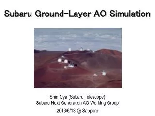
Subaru GLAO Simulation Shin Oya (Subaru Telescope) 2012/10/16 @ Hilo
Outline • What is Ground Layer Adaptive Optics (GLAO)? • a type of wide-field AO • Mauna Kea seeing (which determines GLAO performance) • Simulation to evaluate performance • Seeing model, configuration • Correction • wavefront error (WFE) • profile (moffat FWHM; ensquared energy) • wavelength dependency, zenith angle dependency • Field-of-View • mechanical limit: Cs 8.6’φ ⇒ 20’ φ w/o ADC (cf. Ns 4’φ) • constraint from performance? • Adaptive Secondary Mirror (ASM) application
What is GLAO? Tomography Wide-field AO (incl. GLAO) needs • Considering 3D structure of atmospheric turbulence • Multiple guide stars GLAO correction
Mauna Kea seeing: overall profile suitablefor GLAO • Free atmosphere turbulence: weak • Ground layer turbulence: strong altitude: log 10km Mauna Kea (long dashed line) MASS-DIM 1km Ground layer 250m = (0m+500m)/2 strength: linear TMT 13N Els+09, PASP,121,527 30x10^-14 m^(1/3)
Mauna Kea Seeing: ground layer suitablefor GLAO • Concentrated close to the surface • Summit ridge (~70 m above Subaru) • Chun+09,MNRAS,394,1121 • - SLODAR(~2yr) • - LORAS(~1yr) • TMT site (~90m below Subaru) • Els+09, PASP,121,527 - MASS-DIMM (~2yr) - SODAR (~2yr) 1" SODAR 0 200m ground layer < 100m ground layer < 80m
Seeing measurement plan at Subaru Grant-in-Aid (Houga) from this FY Local ground-layer at Subaru? - 70m below and leeward of the ridge (laminar flow?) - fine resolution data for more detailed simulation Luna Shabar (PTP) by Univ.BC optical: 1 ~ 1000m SNODAR by Univ. NSW acoustic: 10 ~ 100m
RAVEN seeing model D. Andersen+2012,PASP,124,469 - based on TMT site testing profile at 13N (Els+09,PASP,121,527) - IQ statistics difference between 13N profile and Subaru is attributed to ground layer Fractional Layer Strength seeing percentile increased to match Subaru IQ statistics fwhm 0.53" 0.66" 0.85" TMT site testing profile ratio
Subaru GLAO configuration tentative r = 5 arcmin 7.5 arcmin 10 arcmin DM: 32 act. Across @ -80m • RAVEN seeing: • good: 0.52” • moderate: 0.65” • bad: 0.84” 1 reconstruction layer (0m) ★: HoGS +: TTF-GS (50" inside of LGS) ■: PSFeval.(toward GS) ▲: (between GS) *: DM fitting
Seeingdependence of WFE difference by FoV size (color) is small seeing bad (0.84") moderate (0.65") good (0.52") tip/tilt~ higher order (half & half contribution) FOV: blue:φ=10arcmin、green: φ=15arcmin、red:φ=20arcmin WFE order: ○: all order、☆: tip/tilt removed= higher order Seeing: ×
Seeing dependence of FWHM FOV:blue:φ=10arcmin、green:φ=15arcmin、red:φ=20arcmin GLAO: ○、 Seeing:×
Seeingvs FWHMratio (GLAO/seeing) the better seeing is, the more effective GLAO correction is. FOV:blue:φ=10arcmin、green:φ=15arcmin、red:φ=20arcmin
Seeingvs EsqEratio (GLAO/Seeing) FoV: 15' f width:blue: 0.24"、green: 0.36"、red: 0.48"
Zenith angle dependence of FWHM effective turbulence height increases Preliminary! theoretical @ ZA<30 moderate seeing FoV: 15' f width: red solid-line: GLAO (center)、blue dashed-line: Seeing black dotted-line: theoretical (seeing)
Comments on the noise FA: free atmosphere GL: ground layer Seeing: s2total = s2atmFA + s2atmGL GLAO: s2WFE = s2atmFA + (s2sense+ s2fit+s2delay+s2etc) WFE (sWFE)increase • limit mag (ssensor): 8% by R=18 (TTF, 10mag LGS), RN limit • HoWFS order (sfit): ~0% by 8x8 R=15 ⇔ 32x32 R=13 • frame rate (sdelay): 8% by 200Hz ⇒ 50Hz(gain=0.5) corrected (residual of AO system error) performance littlechange if seach < satmFA uncorrected (dominant) seeing determines performance
Bright NGS vs Typical LGS typical case: moderate seeing (0.66"), FoV 15'f WFE [nm]: Tot: 1274±325, TT: 955±395, Ho: 802±129 • NGS sensor noise free (R=10) WFE [nm]: Tot: 737±95, TT: 515±122, Ho: 519±47 • LGS R=10, NGS(TTF) R=18mag WFE [nm]: Tot: 783±127, TT: 578±161, Ho: 517±47 WFS parameters: SH, 200Hz, gain=0.3, RN=0.1e-, 512x512pix
Possible observation modes by ASM 1. GLAO @ Cs • seeing improvement over wide FoV 2. On-Source Single NGS @ Cs, Ns • high SR for bright on-source NGS • reduction of thermal background at l > 2mm 3. Single Conjugate Laser Tomography (SCLT) @ Cs,Ns • better SR than on-source single LGS • as close to on-source single NGS as possible • Multi-Conjugate Laser Tomography (MCLT)? • to increase FoV > 1 arcmin
14. On-source bright NGS ASM NGS (R~8mag) NGS188 LGS188 GLAO - LGS (Reff~10mag) - TTFGS (R ~ 18mag) FoV: 15' f Seeing @ 0.5mm: good (0.52")、moderate (0.62")、bad (0.84") System: solid: ASM、dashed: GLAO 、LGSAO188: GLAO
Summary • GLAO: Ground Layer Adaptive Optics • a wide-field AO correcting ground-layer turbulence only • Mauna Kea seeing is suitable for GLAO • Expected performance of GLAO by MAOS simulation • Seeing model: TMT (13N) + GL to match Subaru IQ statistics • Parameters: 32 elem, 4GS (NGS or LGS+TTF), 200Hz, 0.1e-RN • Correction • FOV: 15' Φ, FWHM < 0.2" @ K-band: 50%ile;0.65"@0.5mm • Field-of-View • mechanical vignetting by the telescope & optical design of the instrument limit FoV (not GLAO performance) • Other possible observation modes by ASM • On-source bright NGS • FOV: 1' Φ, SR ~ 0.9 @ K-band : 50%ile;0.65"@0.5mm • Laser tomography • single conjugate (ASM only), multi conjugate (in future?)
AO types finer correction (increasing the number of elements) Wide field AO (Subaru ngAO) HiCIAO/SCExAO RAVEN LGSAO188 more layer correction (increasing the number of DM & WFS)
世界のAOの分布 NGAO(Keck'15) GALACSI(VLT'14) ATLAS(EELT) LTAO(GMT) GPI(GS'13) SPHERE(VLT'11) PFI(TMT) EPICS(EELT) 濃色:8m以下 淡色:30m級 MAD(VLT) GeMS(GS) NFIRAOS(TMT) MAORY(EELT) GRAAL(VLT'14) D2ndM(MMT, LBT) IMAKA(CFHT'16) D4thM (EELT) D2ndM(GMT) CONDOR(VLT'16) IRMOS(TMT) EAGLE(EELT) Standard ...
広視野AO: MCAO FoV: 2 arcmin diffraction-limited survey possible multiple layers & multiple correctors conjugated RTC multiple WFSs wide-field instrument
広視野: GLAO FoV: 10 arcmin fwhm: < 0.4 [arcsec] survey possible ground-layer correction only single corrector (deformable 2ndry) WFS(s) wide-field instrument
広視野AO: MOAO FoR: 3 arcmin FoV: a few arcsec diffraction-limited targeted only each object direction multiple WFSs open loop each DM IFU spectrographs
3. Seeing simulation (1) MAOS calculation reproduces seeing @ 0.5 mm, if FWHM is scaled by 1.22 (2) λ dependence seeing ∝ λ^-0.2 fitting: -0.3 ~ -0.4 i.e., under estimate at longer wavelength RAVENis used for Subaru simulation red: RAVEN: good(dashed; r0 ○), moderate(solid; r0 □), bad(dotted; r0 ×) blue: Gemini: low gray-zone(solid), mid gz(dashed), high gz(dotted); r0 □ green: IMAKA: moderate(solid); r0 □
8. Seeing WFE vs WFE ratio (GLAO/Seeing) difference by FoV size (color) is small FOV: blue:φ=10arcmin、green: φ=15arcmin、red:φ=20arcmin Order: ○: all order、☆: piston/tip/tilt removed= higher order
7. Seeing dependence of EsqE width:blue: 0.24"、green: 0.36"、red: 0.48" GLAO: ○、Seeing: FoV: 15' f
11. Field dependence of WFE Good seeing (0.52") Moderate seeing (0.62") Bad seeing (0.84") 1500nm 0nm 0 1 1 0 1 0 normalized radius FoV: blue: 10'φ、green: 15'φ 、red: 20'φ direction: □: toward GS、△: between GS GLAO: solid lines、seeing (uncorrected): dotted lines
12. Dependence on the system order FoV:15' f moderate seeing At shorter wavelength, lower order system performance is worse. The system order will be determined by LGS brightness and WFS noise. red: 32 act. across DM (& WFS)、blue: 10 act. across DM (& WFS) Note that the result for the combination of high-orderDM (32 act. across) and low-order WFS (10 act. across) is the same as 10 act. acrossDM (&WFS).