Download
1 / 19
190 likes | 220 Views
Learn about the operation of the ALICE Spectrometer Dipole and Compensators in IP2, as well as the challenges faced in the LHCb Spectrometer in IP8. Includes details on crossing angles, beam separation, and polarity changes.

E N D
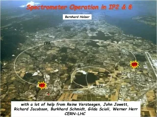
Spectrometer Operation in IP2 & 8 Bernhard Holzer IP5 IP8 IP2 IP1 * with a lot of help from Reine Versteegen, John Jowett, Richard Jacobson, Burkhard Schmidt, Gilda Scioli, Werner Herr CERN-LHC
ALICE The Straight Forward One IP2 compensators Spectrometer Dipoles The ALICE Spectrometer Dipole and Compensators form a tiny little crossing angle bump in the vertical plane ... at constant field. * vert. crossing angle at 450 GeV: y’ = +/- 1089 μrad * “ at 4 TeV: y’ = +/- 122.5μrad
ALICE spectrometer & ext. bumps court. Reine Versteegen Injection, 450 GeV: beam separation at any encounter required The vertical bump, created by the spectrometer dipole is combined with an external vertical crossing angle bump and a horizontal separation bump: * spectrometer dipole: vert. crossing angle at : y’ = +/- 1089 μrad * external vert. crossing angle bump: y’ = +/- 170μrad * external hor. separation bump: Δx=+/- 2mm IR2, p-p physics in 2012 - γεp = 2.5 μmrad Injection – β*= 10 m, θy = +170 + 1089 μrad
ALICE spectrometer & ext. bumps Collision, 4000 GeV: beam separation at IP2 collapsed, beam separation at parasitic encounters via vert. crossing angle bump, Crossing angle due to the spectrometer scales down as 1/E * spectrometer dipole: vert. crossing angle at : y’ = +/- 122.5 μrad * external vert. crossing angle bump: y’ = +/- 145μrad IR2, p-p physics in 2012 - γεp = 2.5 μmrad Physics – β*= 3 m, θy = 145 + 122.5 μrad
ALICE Polarity Change p-p “Wish List”: change polarity once per collision mode p-p, p-Pb, Pb-p Overall beam geometry is not affected: mirror symmetric situation however: TCT re-alignment required, a bit time consuming Physics – β*= 3 m, θy = 145 + 122.5 μrad TCTs
ALICE p-PB collisions Injection: unchanged, * spectrometer crossing angle y’ = +/- 1089 μrad * external crossing angle: y’ = +/- 170μrad (const. !) * external hor. separation bump: Δx = +/- 2mm Collision: minimise the net crossing angle, external crossing angle bump counteracts the spectrometer IR2, p-Pb physics in 2013 - γεp = 2.5 μm.rad, γεPb = 1.5 μm.rad Physics – β*= 0.8 m, θy = -62.5 + 122.5 μrad
ALICE Polarity Change p-Pb CERN-ATS-Note-2012-039 MD avoid TCT re-alignment at injection & on the ramp (a bit time consuming) IR2, p-Pb physics in 2013 - going into physics • At the end of the squeeze, θy,tot = 145 ± 122.5 μrad. • Depending on the spectrometer polarity, θy,ext is changed from +145 μradto ± 62.5 μrad, to get θy, tot = ± 60 μrad. • → positive polarity implies going through zero external angle, leading to about 1σ separation at the 200ns first two encounters (in the horizontal plane). β*= 0.8 m θy,ext = 145 μrad θy,ext = 0 μrad θy,ext = -62.5 μrad
LHCb: The Challenge IP8: “natural LHC geometry” and the LHCb spectrometer effect Design Orbit: Beam1 crosses at IP8 from ring outside to inside -> negative horizontal angle provided by D1 & D2. The LHCb Spectrometer Dipole and Compensators form a not really tiny little crossing angle bump in the horizontal plane ... at constant field. * hor. crossing angle at 450 GeV: x’ = +/- 2.1 mrad * “ at 4 TeV: x’ = +/- 235μrad * depending oh the dipole polarity
LHC Lattice Layout in IP8 Situation at Luminosity: E=7 TeV, ε=3.0μrad LHCb angle = x’int=+/- 135 μrad, compensated external hor. crossing angle = 0 parasitic encounters are avoided by vertical external crossing of y’=90μrad +/- 5σ beam envelope at IP8, in collision mode crosses mark the 25ns encounters
LHC Lattice Layout in IP8 Situation at Luminosity: combination of hor. & vert. crossing anbgles • Present Situation at collisions ... The diagonal leveling scheme • Eliminate the External H crossing angle • Introduce an External V crossing angle that combines with • LHCb spectrometer to the “diagonal leveling plane”
Situation in IR8 at Injection: Situation at Injection: E=450 TeV, ε=3.0μmrad, LHCb Effect: “internal” horizontal crossing angle = x’ = +/- 2.1 mrad “external” hor. crossing angle to avoid parasitic encounters x’= – 170 μrad const. vertical separation bump Δy = 2mm This combination has to avoid encounters at any position. Vertical plane: +/- 5σ beam envelope at IP8, injection, crosses mark the 25ns encounters Beams are separated at IP and the first encounters #1 ... #4 due to vert. separation. Horizontal plane: LHCb = GOOD LHCb = “good” From encounter #5 on the horizontal crossing bump has to do the job.
Situation in IR8 at Injection: Horizontal plane: LHCb = BAD beam 1 is deflected towards outer side of LHC, the compensators are bending back the orbit -> cross over !! and the external bump is used to deliver after the compensators sufficient separation at the parasitic encounters. +/- 5σ beam envelope at IP8 Beams are crossing over between two 50ns encounters x’= +2.1mrad -170μrad = +1.93 mrad cross over between two 50ns encounters. 50ns 25ns ... for 25 ns bunch spacing parasitic collisions are unavoidable !!
Swapping the Planes ... ? The horizontal crossing angle bump always will have to fight against the bad LHCb polarity. A vertical crossing angle bump does not ! calculate orbits & envelopes for Δx = 2.0 mm, y’ = 170 μrad, LHCb = on = bad vert. crossing angle separates the beams from encounter #4 LHCb internal crossing angle separates the beams at #2 ... #5 Δx = 2mm separates the beams at #1 (i.e. IP) vertical plane horizontal plane: LHCb = good LHCb = bad The scheme works for any LHCb polarity and guarantees sufficient separation at ANY encounter !!
But ... LHC beam screen is not symmetric hor. / vert. Aperture Model for present situation n1 ≈ 7 Aperture Model for swapped situation n1 ≈ 4.5 n1 ≈ 7 n1 ≈ 4.5
III). Optimising Y’: Using the mcbx coils to flatten the vert. crossing bump inside the triplet? Reducing the crossing angle to the bare minimum ... For ε = 3.0, scanning the vertical crossing angle ... with slight optimism. on_xv i= 0.8 = 136 μrad + LHC b= 108 μrad
V) Aperture Scans ε = 3.0μrad Cor = 3.0 Cor = 2.5 Cor =2.0 Cor =1.5
VI.) ... and finally the measurements YASP-Extraction: (vert.) orbits beam1 absolute value -11mm reaching the aperture limit in 1st direction -5.4mm reaching the aperture limit in 2nd direction +23.3mm overall amplitude 28.7mm + 2* 4σ β=270m, εn=3.5 -> σ=1.5mm aperture radius = 20.4 mm
cross check & summary Referring to the IP settings of the bump: aperture limits obtained at Δy ≈ + / - 11mm corresponds to 17.8mm at Q2. Overall Aperture: 17.8mm + 4σ = 23.8mm Compared to theoretical expected value: ... Beam Screen Geometry in IP8 hor * vert. = 29mm * 24mm ufffff ... ????? Aperture Need: y’=108 μrad -> Δy = 6.8mm at Q2 Overall Aperture Measured = 24 mm In other words: applying 108μrad gives us still margin for 17 mm ... corresponding to 12σ (ε = 3.0) Q2 IP vert. Separation Bump +/- 11 mm 29mm 24mm
cross check & summary • * ALICE Spectrometer needs polarity switch once per collision mode • TCT re-alignment needed in all machine procedures • fast procedure established (and already used in 2012) for Pb-Pb / p-Pb runs • vertical deflection does not harm operation • * LHCb Spectrometer needs polarity change every “n” weeks, • horizontal crossing scheme is not compatible with 25ns bunches • new procedure has been established combining the unavoidable hor. crossing with • vertical crossing scheme and a hor. offset. • Problem: Aperture, but seems feasible. * h=9 scheme gives us even smaller emittances at 450 GeV and makes the new procedure quite promising. h=9, ε = 1.5 μrad