Download
1 / 39
410 likes | 681 Views
KOMPSAT- I and OSMI. H. Y. Paik Korea Aerospace Research Institute 1998. 7. 25. CONTENTS. 1. KOMPSAT OVERVIEW 2. Electro-Optical Camera(EOC) OVERVIEW 3. Payload Data Transmission Subsystem(PDTS) 4. Ocean Scanning Multispectral Imager(OSMI) 5. KOMPSAT II PLAN 6. SUMMARY.

E N D
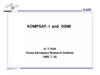
KOMPSAT- I and OSMI H. Y. Paik Korea Aerospace Research Institute 1998. 7. 25.
CONTENTS 1. KOMPSAT OVERVIEW 2. Electro-Optical Camera(EOC) OVERVIEW 3. Payload Data Transmission Subsystem(PDTS) 4. Ocean Scanning Multispectral Imager(OSMI) 5. KOMPSAT II PLAN 6. SUMMARY OCARE-98/NTU
KOMPSAT OVERVIEW • Mission : Earth Remote Sensing(EOC, OSMI) • and Space Experiment(SPS) • Mission Orbit • - Circular, Sun-synchronous • - 685km altitude, 98.13 deg. Inclination • - 10:50AM Equatorial Crossing(Ascending) • - 98.5 min orbit period • - 2 day (45 deg. Roll) / 3 day (30 deg. Roll) revisit • Launch date : August, 1999 ( 3 year life time) • Spacecraft Mass : About 500 kg(including 73 kg propellant) • Joint Development with TRW OCARE-98/NTU
KOMPSAT OVERVIEW(OPERATION) Payloads Ground Station • Electro-Optical Camera(EOC) • Pushbroom Scanned • Off-pointed for Cartography • 15km swath 6.6m GSD(nadir) • 2 minute contiguous duty cycle • Payload Data Transmission • Subsystem(PDTS) • X-band system for image data • Solid State Recorder(2.5Gbit) • 10% duty cycle • Mission and Control Center • RF Communications (S-Band) • Satellite Operations • Mission Planning • Spacecraft Simulator/Training • Ocean Scanning Multi-spectral • Imager(OSMI) • Cross Track Scanned • 800km swath, 1km GSD • 20% duty cycle • Science Physics Sensor(SPS) • Ionosphere Measurement Sensor • High Energy Particle Detector • 100% duty cycle • Image Processing Center • RF Communications (X-Band) • Image Processing • Product Generation • Data Storage and Distribution • External Interface • Users • Additional Image Acquisition • or LEOP stations OCARE-98/NTU
KOMPSAT OVERVIEW(OPERATION) OCARE-98/NTU
KOMPSAT OVERVIEW(GROUND STATION) OCARE-98/NTU
KOMPSAT OVERVIEW(SPACECRAFT) Space Physics Sensor L/V Adapter Solar Array BUS Electro Optical Camera Ocean Scanning Multi-spectral Imager OCARE-98/NTU
KOMPSAT OVERVIEW(PAYLOAD) • KOMPSAT-I Payload Configuration EOC LRC Weight Power EOC 35Kg 52W LRC 18Kg 30W SPS 7.6Kg 16W PDTS 14.5Kg 63W Total 100Kg 159W SPS PDTS OCARE-98/NTU
TOP LEVEL MISSION OVERVIEW • Korea Cartography Mission - Provide images for cartography which will allow the production of a map of Korea to a 1:25000 scale standard • Ocean Color Monitoring Mission - Image oceans to support biological oceanography - 6 spectral bands, large scale multispectral images • Scientific Payloads Accommodation Mission - Accommodate customer-furnished scientific payloads • Ionosphere Measurement Sensor (IMS) - Globalized measurement of ionized layer in KOMPSAT orbit • High Energy Particle Detector (HEPD) - Globalized measurement of high energy particles in KOMPSAT orbit OCARE-98/NTU
EOC OVERVIEW • The KOMPSAT EOC mission objective is to provide images for the production of scale maps including digital elevation models. • The EOC Design Specification • Panchromatic spectral band: 510 - 730 nm • Ground Sample Distance(GSD); 6.6m in nadir view • Swath width: >15Km in nadir view • MTF: >10% at Nyquist frequency • SNR: >50 • Data Rate: <25Mbps OCARE-98/NTU
EOC OPERATION CONCEPT • Cartography Data Collection • Operational Control • Mode Control • 2 minute(contiguous) duty cycle per orbit • Programmable gain control • Spacecraft roll control for swath pre-position • Real time data downlink via X-band in view of • KGS • Capability to store EOC data in PDTS SSR within • storage capacity and duty cycle constraints • On-board Calibration: dark & solar calibration OCARE-98/NTU
PDTS OVERVIEW • The KOMPSAT PDTS mission objective is to provide X-band downlink to transmit EOC/OSMI image data and On-Board-Computer(OBC) data to Korea Ground Station(KGS). • PDTS Design and Function • Formatter/Multiplexer Unit(FMU) • to format and encode image data and telemetry data in CCSDS grade 2 (Input Data Rate; EOC: 25Mbps, OSMI: 1Mbps, OBC: 1.5Mbps) • to store image data in Solid State Recorder(SSR) with the storage capacity of 2.5Gbit@EOL for later playback downlink • Transmitter • QPSK modulation • RF Assembly • X-band Omni Antenna • Data Transmmision Rate : 45Mbps • Data Reception Contact Area Radius from KGS : 1500Km • Link margin > 3dB with BER of 10-6 • Duty Cycle per Orbit : 10% OCARE-98/NTU
OSMI MISSION • The KOMPSAT OSMI Mission objective is to provide ocean color measurements for biological oceanography. • The OSMI primary spectral bands selected to meet the mission goal are: Band # Bandwidth Sensing Objective B1: (443 nm) 20 nm Concentration of chlorophyll B2: (490 nm) 20 nm Concentration of pigment B3: (510 nm) 20 nm Turbidity of chlorophyll B4: (555 nm) 20 nm Turbidity B5: (670 nm) 20 nm Calibration of atmospheric effect B6: (865 nm) 40 nm Calibration of atmospheric effect OCARE-98/NTU
OSMI OPERATION CONCEPT • Ocean Color Monitoring Data Collection • Operational Control • Mode Control (20% duty cycle) • Selectable bands(6 bands within 400-900 nm) • Programmable gain control • Collection during vertical viewing at specified performance • Real time data downlink via X-band in view of ground station • Stored data via PDTS SSR out of view within storage (2.5Gbits @EOL) and duty cycle constraints OCARE-98/NTU
OSMI OPERATION CONCEPT • OSMI Operation Modes once per orbit, at the earth north pole Solar Calibration Safe/Hold Imaging Standby 20% duty per orbit, image data collection SOH data downlink commands uplink Dark Calibration Reset before and after imaging mode OCARE-98/NTU
OSMI PERFORMANCE OCARE-98/NTU
OSMI DESIGN • OSMI Optical Layout APERTURE CELL (WITH CORRECTOR LENS) FIRST FOLD MIRROR CELL FORE-OPTICS CELL WINDOW CELL DARK CALIBRATION CAVITY SCAN FIELD OF REGARD RANGE LIMIT SLIT CELL COLLIMATING CELL GRATING CELL SCAN MIRROR RE-IMAGING CELL SOLAR CALIBRATION CAVITY SECOND FOLD MIRROR CELL VIEW FROM +X ( COVERS REMOVED) OCARE-98/NTU
OSMI PHOTON COLLECTION OCARE-98/NTU
Focal Plane Module o CCD o Electronics Data Buffer o Data Compression Processor Scan Drive Electronics Power Converters On/Off Relay OSMI DESIGN • OSMI Electronics Block Diagram LSA LEA Video Clock Video Electronics Power (VE) FPA Gain Spacecraft Timing Data Offset Data Spectral PDTS Data 1553B Command, Temp. SOH Telemetry LSA Sensors o Temp. Sensor Htr Time Mark, o Heater Safe Hold Power Motor Scan Driver Drive Assembly OBC o Motor o Pos. Sensor Position ON/OFF Command Survival Heater ON/OFF & Thermostat Status 28VDC OCARE-98/NTU
BAND SELECTION CHARACTERISTICS 768 CCD Package Top view 384 96km Fanout Substrate Super Pixel 1km 768 Storage Register 96 Storage Register Spatial Temperature Sensor CCD Active Image Area 1km 192 900nm Spectral 400nm 2.6nm • Minimum Selectable Band = 2.6 nm X 2 = 5.2 nm • Maximum Selectable Band = 2.6 X 64 =140 nm . . OCARE-98/NTU
OSMI BAND SELECTION CAPABILITY • OSMI has on-orbit spectral band selectibility via Ground Command after launch. • Any 6 spectral bands can be selected in the spectral range from 400 nm to 900 nm which is divided into 192 spectral pixels. • There are always 6 bands without overlap among the bands • Band Center: 6 positions with 2.6nm accuracy • Band Width: minimum 5.2 nm, maximum 166.4 nm • Command is valid in the standby mode only. • The above on-orbit band selectibilty provides - great flexibility in Ocean Color Monitoring - research opportunities to support the next generation sensor design OCARE-98/NTU
OSMI MISSION PARAMETER OCARE-98/NTU
OSMI MEASURED PERFORMANCE • The instrument performance is measured on-ground for 8 basic spectral bands within 400 nm ∼ 900 nm including the primary bands. (1)Spectral Band Characteristics OCARE-98/NTU
OSMI MEASURED PERFORMANCE(Con’t) (2) OSMI radiometric characteristics OCARE-98/NTU
OSMI MEASURED PERFORMANCE(Con’t) (3) MTF The satellite-level MTF is predicted as shown in the Figure 3.3 based on the measured values of instrument level MTF, space environment (temperature change and vacuum) effect analysis and satellite motion (jitter & smear) effect analysis. OCARE-98/NTU
KOMPSAT - II PLAN • Scheduled to be launched in 2002 - 2003 period • KARI will be responsible for the development. • Heritage : KOMPSAT - I • Estimated weight & power: 800kg / 800watt • Main Payload : Multi-Spectral Camera (Pan: 1m GSD, 4 band multi-color: 4m GSD) • Secondary Payload : under- study OCARE-98/NTU
SUMMARY • KOMPSAT- I is scheduled to be launched in August 1999 (KOMPSAT II IN 2002 - 2003 Period) • OSMI will perform worldwide ocean color monitoring. • OSMI major specification • Orbit : 685Km altitude, 10:50AM ascending, Sun Synchronous • GSD : 1Km, Swath Width: 800Km • Spectral Band: 6 bands • Duty Cycle: 20% • On-board Image Data Storage: 2.5Gbits at the end of life time • OSMI has On-orbit spectral band selection capability. • Selection of 6 bands from 400 nm to 900 nm • Great flexibility for ocean color monitoring and its applications OCARE-98/NTU
KOREA MULTI-PURPOSE SATELLITE KOREA AEROSPACE RESEARCH INSTITUTE OCARE-98/NTU
KOREA MULTI-PURPOSE SATELLITE S/C BUS Solar Array Space Physics Sensor Electro Optical Camera L/V Adapter S-band Antenna Ocean Scanning Multi-spectral Imager OCARE-98/NTU
KOMPSAT APPLICATIONS OCARE-98/NTU
KOMPSAT APPLICATIONS OCARE-98/NTU
KOMPSAT FM UNDER INTEGRATION Payload Module Proto-Flight Model in Final Assembly Equipment Module Propulsion Module OCARE-98/NTU
Satellite Assembly, Integration & Test Center OCARE-98/NTU
KOMPSAT AI&T FACILITIES Orbit Environment Test - Thermal-vacuum Chamber - Thermal-shock Chamber - Bake-out Chamber OCARE-98/NTU
KOMPSAT AI&T FACILITIES Integration & Assembly - Angular accuracy : 1/360 - Position Accuracy : 50 OCARE-98/NTU
KOMPSAT AI&T FACILITIES (continued) Launch Environment Test - Vibration Test System - Mass Property System OCARE-98/NTU
KOMPSAT AI&T FACILITIES (continued) EMI/EMC Test - Anechoic Chamber - 13(L)x12(W)x7(H)m OCARE-98/NTU
Payload Assembly and Test Lab. Optical Instrument Assembly and Test Lab. - Large Aperture / High Precision Optics - Surface Quality Measurement - Alignment - Performance Test (Parts / E-O System) - Vibration Control / Clean Room Facility • Electronics Assembly and Test Lab. • - General P/L Electronics Test-bed • - Focal Plane Assembly Test & Analysis • Sensor Characteristics • FPE and Analog Signal Processor • - Payload Data Transmitter Test & Analysis Flight Software Test Lab. - Flight Software Design and Test for the On-board Computer and Payload Instruments - Development of Software Test-bed OCARE-98/NTU
KOMPSAT GROUND STATION Mission Control & Data Receiving / Processing Station OCARE-98/NTU