Download

1 / 25
250 likes | 373 Views
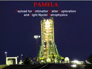
PAMELA (Particle Accelerator for Medical Applications) is pioneering the design of an accelerator facility specializing in proton and carbon therapy using non-scaling Fixed-Field Alternating Gradient (NS-FFAG) technology. The project aims to create a prototype machine capable of biological studies that meets clinical requirements for intensity-modulated particle therapy (IMPT). Key challenges include managing resonance crossing during slow acceleration, maintaining cost-effectiveness, and achieving precise dose uniformity. Collaborations across renowned institutions enhance the research and development efforts.

E N D
PAMELAan overview Takeichiro Yokoi JAI, Oxford University
Introduction • PAMELA(Particle Acceleratorfor MEdicaL Applications ) aims to design particle therapy accelerator facility for proton and carbon using NS-FFAG with spot scanning Prototype of non-relativistic NS-FFAG (Many applications !! Ex. proton driver, ADS) • It also aims to design a smaller machine for biological study as a prototype. • Difficulty is resonance crossing acceleration in slow acceleration rate • As a practical machine, economy is an issue.
Collaboration In this session …. PAMELA (PM: K.Peach) Rutherford Appleton Lab Daresbury Lab. Cockcroft Inst. Manchester Univ. Oxford Univ. John Adams Inst. Imperial College London Brunel Univ. Gray Cancer Inst. Birmingham Univ. FNAL (US) LPNS (FR) TRIUMF (CA) T.Yokoi … Overview A.Kacperek … Medical requirement H. Witte … Magnet option C. Beard … RF option S. Sheehy … Lattice
Clinical requirements (1) : Spot scanning Spot scanning can fully exert the advantage of particle therapy and pulsed beam of FFAG matches well to the treatment Typical voxel size : 4mm 4mm ~10mm 10mm Energy range : 70MeV~250MeV Typical @patient : ~1m Extraction scheme : Fast extraction Beam emittance : ~10 mm mrad (normalized)
Synchrotron & cyclotron SOBP is formed by superposing Bragg peak Integrated current Gate width controls dose time FFAG Step size controls dose Integrated current time Clinical requirements (2): IMPT Dose uniformity should be < ~2% To achieve the uniformity, precise intensity modulation is a must IMPT (Intensity Modulated Particle Therapy) Beam of FFAG is quantized. Good stability of injector and precise loss control are indispensable for medical applications At the moment, instead of modulating the intensity of injected beam, shooting a voxel with multiple bunches is to be employed. “How high is the intensity of a beam bunch?” “Analog IM” “Digital IM”
Medical requirement (2): IMPT • To investigate the requirement of injector, formation of SOBP in IMPT was studied using analytical model of Bragg peak • The study of beam intensity quantization tells intensity modulation of 1/100 is required to achieve the dose uniformity of 2%.(minimum pulse intensity:~106 proton/1Gy) Monitor is a crucial R&D item of PAMELA • If 1kHz operation is achieved, more than 100 voxel/sec can be scanned even for the widest SOBP case. 1 kHz repetition is a present goal (For proton machine : 200kV/turn)
Injector Injector can preferably cope with proton and heavy ion injection (ICL group lead by J.Pozinsky investigating the scheme ) • Two injectors are to be employed: cyclotron for proton, RFQ for HI • Typical beam emittance from injectors : 1 mm mrad (normalized) • Tracking study of RFQ line is undergoing. (transmission efficiency> 75% is achieved • Stability of intensity is typically less than 5%
Lattice At present, two different types of lattice are proposed for NS-FFAG of non-relativistic particle Linear lattice (by E.Keil et al.) Small excursion, large tune drift, short drift space, ordinary combined function magnet (2) Non-Linear Lattice (by C. Johnston et al.) * sextupole for chromaticity correction Large excursion, small tune drift, long drift space, wedged combined function magnet † In lattice design study, we are now focusing on the understanding of dynamics of proton NS-FFAG : dynamics of slow resonance crossing acceleration, field quality, tolerance etc…
Test Lattice As a test lattice, tune stabilized lattice proposed by C. Johnston was employed • Wedge shaped combined function magnet (quadrupole) • small number of cell (#cell:14), and long straight section(>1m) • Long excursion(>80cm) variable energy extraction, rf cavity • Relatively weaker field gradient(4.5T/m), Max dipole field:1.5T (on orbit)
Tune of test lattice • Using ZOGUBI, lattice building was carried out. • Horizontal tune can be well reproduced. However, to reproduce vertical tune, wedge angle was needed to be tweaked. The source of discrepancy must be identified. One possible source is the fringing field model • The beam dynamics is basically subjected by the tune As long as tune is similar, the dynamics can be discussed in a similar way. Original design ZGOUBI result
Acceleration (perfect lattice) • Horizontal beam blows up slightly ( amplitude wise:~6% for 400MeV acceleration • It is caused by the transverse kick by rf acceleration due to the tilted orientation of accelerating field to the beam axis. Arrangement of rf cavity could affect the intrinsic horizontal beam blow up, But this effect is not important 210keV/turn
Acceleration (Vertical) • The beam acceleration was carried out for vertically distributed beam with various positioning error and accelerating rate (horizontal beam size: 0) • Beam blow-up is clearly observed at integer resonance ‘Microscopic’ study is required to understand the blow-up process V:260keV/turn
Integer resonance crossing (1) R. Baartman proposed a simple formula to evaluate the amplitude growth during resonance crossing For integer resonance Q, (m=1, n=Q) Stronger focusing suppresses amplitude growth through smaller Intrinsic parameter of lattice Design parameter
kV/turn kV/turn (m) (m) 320 320 320 320 260 260 260 260 210 210 210 210 90 90 70 70 90 90 70 70 70 70 90 90 Theoretical value Integer resonance crossing (2) • Tracking study was carried out around integer resonance(Q=4,3) • 3 acceleration rate, 2 alignment error were examined • 100 different lattice configurations For single integer resonance crossing, Baartman’s formula can estimate the growth rate
(n=2Q) (=2Q) Half integer resonance crossing Lattice parameter Design parameter • By introducing focusing error to individual magnet, blow-up rate was estimated • 100 different error settings were examined . Baartman’s formula can somehow evaluate the blow-up rate of half integer resonance
Q=2.5 Structure resonance Ncel 14 4Q=14 (2Q=7) is structure resonance Q=4 Q=3.5 Dynamic aperture 20mm mrad Q=3 Dynamic aperture Q=2.5 Q=3.5 210kV/turn Even with only positioning error, resonance is excited at Q=3.5 **Field gradient error caused by the positioning error is<10-3
Integer resonance (=6,1mm mrad.norm) eV(MeV/turn) pos(m) Requirements for lattice • Up to half integer resonance, Baartman’s formula can somehow evaluate the blow-up rate. • For slow acceleration case, (~200keV/turn) integer resonance crossing should be avoided. • Single half integer resonance crossing would be tolerable • Structure resonance also should be circumvented. ** Contribution of higher order components, ex fringing field, remains for future study “Is there doable lattice option at the moment ??” Linear NS-FFAG (200kV/turn, average B0;n,, w/o ∆B1,x=100m)
Lattice option S.Machida proposed semi-scaling FFAG for proton therapy (up to decapole) • Tune drift ∆<1 (no integer crossing, no structure resonance crossing) • Orbit excursion ~30cm • Long straight section (>2m) H.Witte (magnet), S.Sheehy (lattice)
1/0 1/0 :200kV/turn :50kV/turn 1/0 eV/turn(MeV) ∆B1/B1 ∆B1/B1 ∆B1/B1 ∆B1/B1 Acceleration Rate (1) Half integer resonance eV/turn (MeV) • Nominal blow-up margin : 5 (1mm mrad 5mm mrad) • With modest field gradient error (210-3), acceleration rate of 50kV/turn can suppress blow up rate less than factor of 5. • For the considered range, 3rd integer resonance will not cause serious beam blow-up (2) 3rd integer resonance 1/0-1 eV/turn (MeV) ∆B2/B2 Required accelerating rate : >50kV/turn
Energy Option 2 Energy Option 1 time 1ms time 1ms Option 1: P Nrep2 Option 2: P Nrep Acceleration Scheme Repetition rate: 1kHz min. acceleration rate : 50kV/turn (=250Hz) How to bridge two requirements ?? Low Q cavity (ex MA) can mix wide range of frequencies Multi-bunch acceleration is preferable from the viewpoint of efficiency and upgradeability
∆f 4 fsy Multi-bunch acceleration Multi-bunch acceleration has already been demonstrated 2-bunch acceleration using POP-FFAG (PAC 01 proceedings p.588) In the lattice considered, typical synchrotron tune <0.01 more than 20 bunches can be accelerated simultaneously (6D Tracking study is required) “Hardware-wise, how many frequencies can be superposed ??”
Extraction (5.5MHz) 50kV Injection(2.3MHz) 50kV Test of multi-bunch acceleration PRISM RF • PRISM rf can provide 200kV/cavity • It covers similar frequency region • Brf-wise, MA can superpose more than 20 bunches Now, experiment using PRISM cavity is under planning (possibly in this October)
Summary • PAMELA intends to design particle therapy facility to deliver proton and carbon using FFAG. • Intensive study is going on (dynamics, rf, magnet, clinical requirement etc.) • Lattice requirements is now getting clear. • For acceleration, multi-bunch acceleration provides efficient and upgradeable option. By the end of next year , hope an doable overall scenario is proposed .
dx: 100µm(RMS) rf: 5kv/cell dx: 10µm(RMS) dx: 1µm(RMS) Acceleration
Acceleration (Horizontal) • The beam acceleration was carried out for horizontally distributed beam (Vertical beam size: 0) • For horizontal motion, beam blow up is controllable. (Half integer resonance affect slightly for the case of positioning error.) • The blow up should be checked with realistic distribution (finite beam size for both direction) V:260keV/turn