Download
1 / 1
40 likes | 291 Views
XATL1 200 m. XATL2 10 m. XATL6 13 m. XAVB. XATL3 17 m. XASB. XATL4 30 m. XATL8 8 m. XATC 1. XATL7 13 m. XATB 1. XATL5 50 m. XAST. XATB 2. XATC 2. XATB 3. To compressors. Cryogenics of European XFEL Accelerator Module Test Facility.

E N D
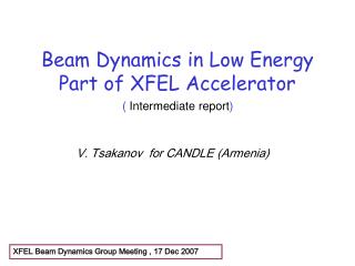
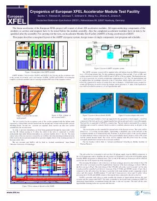
XATL1 200 m XATL2 10 m XATL6 13 m XAVB XATL3 17 m XASB XATL4 30 m XATL8 8 m XATC 1 XATL7 13 m XATB 1 XATL5 50 m XAST XATB 2 XATC 2 XATB 3 To compressors Cryogenics of European XFEL Accelerator Module Test Facility Bozhko Y., Petersen B., Schnautz T., Sellmann D., Wang X.L., Zhirnov A., Zolotov A. Deutsches Elektronen-Synchrotron (DESY), Notkestrasse 85, 22607 Hamburg, Germany The linear accelerator of the European XFEL project will consist of about 100 accelerator modules. All superconducting components of the modules as cavities and magnets have to be tested before the module assembly. Also the completed accelerator modules have in turn to be qualified after the assembly. For carrying out the tests, an Accelerator Module Test Facility (AMTF) is being constructed at DESY. This paper describes conceptual layout of the AMTF cryogenic system, design issues of single components, test program and schedule. Figure 2 Layout of AMTF cryogenic system The AMTF cryogenic system will be supplied with cold helium from the HERA refrigerator via a ~150 m long transfer line. For the continuous operation of the test hall, 33 g/s of LHe, and cooling capacities of about 3 kW at 40/80 K and 0.5 kW at 4.5 K are needed. The liquefaction rate of 33 g/s is necessary for covering refrigeration requirements at 2 K. The 2 K liquid helium will be supplied there by isenthalpic expansion of the 4.5 K helium, which will be sub-cooled to 2.2 K before the expansion by means of counter flow heat exchangers. A distributed warm compressor system will therefore be used to lower the helium vapour pressure to 31 mbar. Peak liquefaction rates will be levelled by means of a 10 m³ liquid helium tank. Figure 1 Ground plan of the AMTF test hall AMTF includes 2 test cryostats (XATC1 and XATC2) for carrying out the acceptance tests of the cavities in cw-mode, and 3 test benches (XATB1, XATB2 and XATB3) for testing the complete accelerator modules and for carrying out pulsed RF tests of the complete cavities. 40/80K thermal shield Feed Cap Vacuum vessel 40K forward Accelerator module End Cap Feed Box Fixed support 2-phase tube Cavity Movable support Figure 5 Layout of the test bench (XATB) Figure 6 Cryostat-adapter with cavity Figure 4 Flow scheme of the cryostat (XATC) Figure 3 Layout of the cryostat inside ground Each test bench includes a feed cap supported to the ground by a fixed support, a feed box connected to the feed cap by an L-shaped transfer line and an end cap fixed to a movable support. The feed box is connected to XAVB by a transfer line. The test bench is surrounded by a concrete shielding and covered by concrete blocks in order to establish radiation safety in all parts of the test hall. The test benches are also intended for optional tests of the dressed cavities. The cavity will be placed in a ~2.2 m long cryostat-adapter representing a simplified copy of the end part of the accelerator module at its beam leaving side. Positions of all process pipes of the cryostat-adapter are fully identical to those of the feed cap. The cryostat-adapter doesn’t dispose of the 4.5K circuit and the related thermal shield. The cavity will be supplied with RF power from the existing waveguide distribution system for the accelerator modules. The test benches will be built as “in-kind contributions” from Russia (Budker Institute of Nuclear Physics). The test cryostat for the acceptance tests of the cavities equipped with the helium tanks represents a vertical bath cryostat inserted into the ground and covered with movable concrete shielding blocks. In total two cryostats are required. Each cryostat can take four cavities assembled in one cryostat insert. In order to prevent atmospheric air from being penetrated through the main safety valve into the 2K volume staying at 31 mbar, the outlet of the valve is connected to a buffer permanently kept under helium atmosphere at a pressure slightly above 1 bar abs. The main safety valve of the test cryostat is secured by an overflow valve that discharges helium from the LHe vessel to the low pressure manifold at a pressure slightly below of the cracking pressure of the main safety valve. The test cryostats and XATL1 will be built as “in-kind contributions” from Poland (Wroclaw University of Technology). The sub-cooler box is intended to sub-cool the 6 K helium supply from the HERA refrigerator to the 4.4 K temperature and to distribute the sub-cooled 4.4 K helium as well as the 40 K helium supply from the HERA refrigerator to different users. The 4.4 and 40 K return gas from users will be collected and fed into the 4.6 K respectively 80 K return pipes. The incoming 6K helium is sub-cooled in a coil heat exchanger placed on the bottom of the 4.5K LHe sub-cooler vessel and covered by liquid helium. Capacity of the heat exchanger is about 1 kW for the flow rates up to 80 g/s. The total volume of the 4.5K LHe sub-cooler vessel is around 1 m³. In order to make possible controlled cool down or warm up of the 4.5/4.6K and 40/80K circuits of any object connected to the sub-cooler box, the latter is provided with warm helium circuits comprising control valves and flow meters. XASB numbers 33 cold and 9 warm process valves and 16 safety valves protecting the 4.5/4.6K and 40/80K circuits of the transfer lines connected to the sub-cooler box. XASB is provided with valves to make possible the transfer of liquid helium between the tests cryostats and the storage tank XAST. The latter is intended to level peak loads occurring at AMTF by transferring liquid helium, accumulated during idle time, to the test cryostats. The tank will also take liquid helium retaining in the test cryostats after the tests. Figure 7 Flow scheme of the sub-cooler XASB